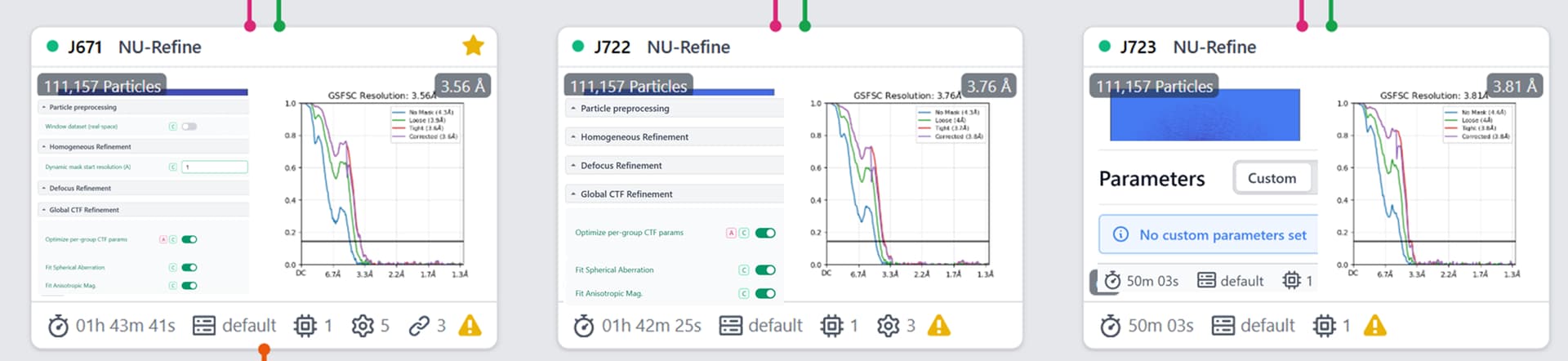
So I am running into a strange issue. I am working with a protein with flexibility. I ran a customised NU refinement, which leads to a resolution of ~3.56 angstrom vs without those custom parameters (~3.76 angs). I am now trying to run 3DVA on the same job, but the job is behaving strangely.
Running the 3DVA job on the default NU job or NU with only minimize over per particle turned on seems to run normally, but the resolution is worse as I mentioned before. Please advise.
As far as I am aware simultaneous Global CTF Refinement does not work with non-uniform refinement. This is likely causing some downstream issues. You have to run the Local and Global CTF refinement jobs separately from the non-uniform refinement. i.e. run Local CTF refinement → Global CTF refinement → Non-uniform refinement
Hope this helped!
For further context:
This is very briefly mentioned in the CTF refinement tutorial (Tutorial: CTF Refinement | CryoSPARC Guide) under the Non-uniform refinement with high-order CTF correction heading.
This is not correct - you can definitely perform global & local CTF refinement on the fly during NU.
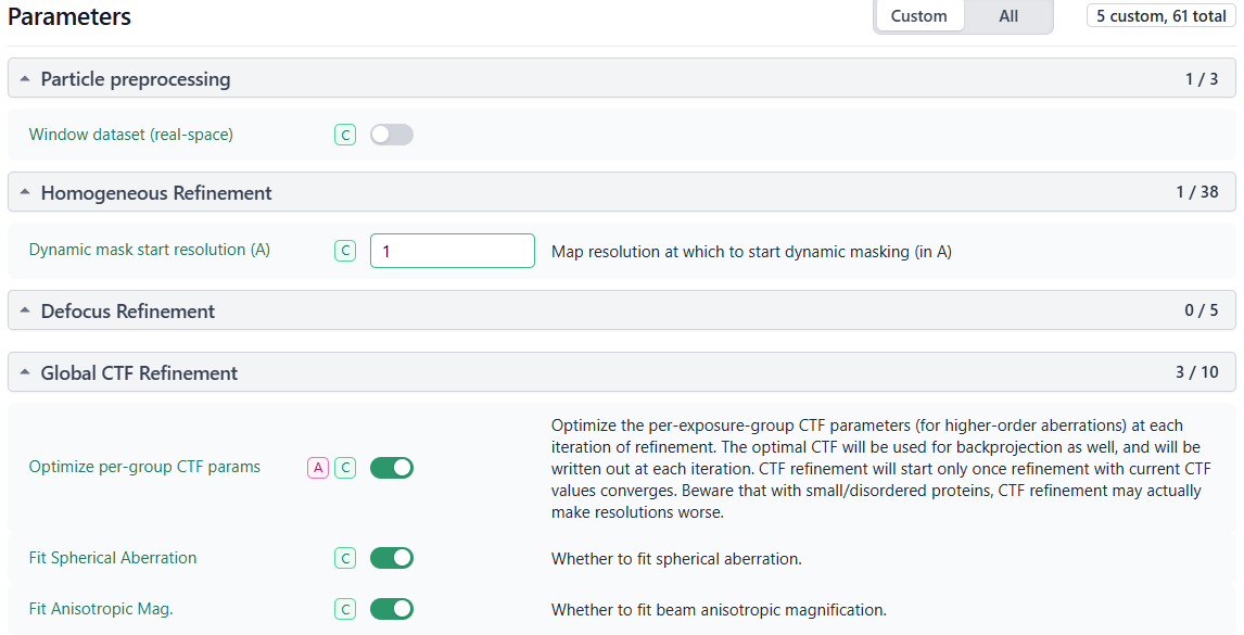
@ZahirSid - if you look at the logs, how did the results of global CTF look? I would not recommend refining spherical aberration or aniso mag at this resolution unless you have a very good reason - it is likely to be unstable, and I suspect this may be the cause of your downstream issues.
In this case I think the CTF refinement tutorial needs an update to the text as it is currently confusing. It currently says:
On-the-fly CTF refinement cannot be done during a Non-uniform Refinement , so particles should be processed through the standalone Local CTF Refinement then Global CTF Refinement jobs first.
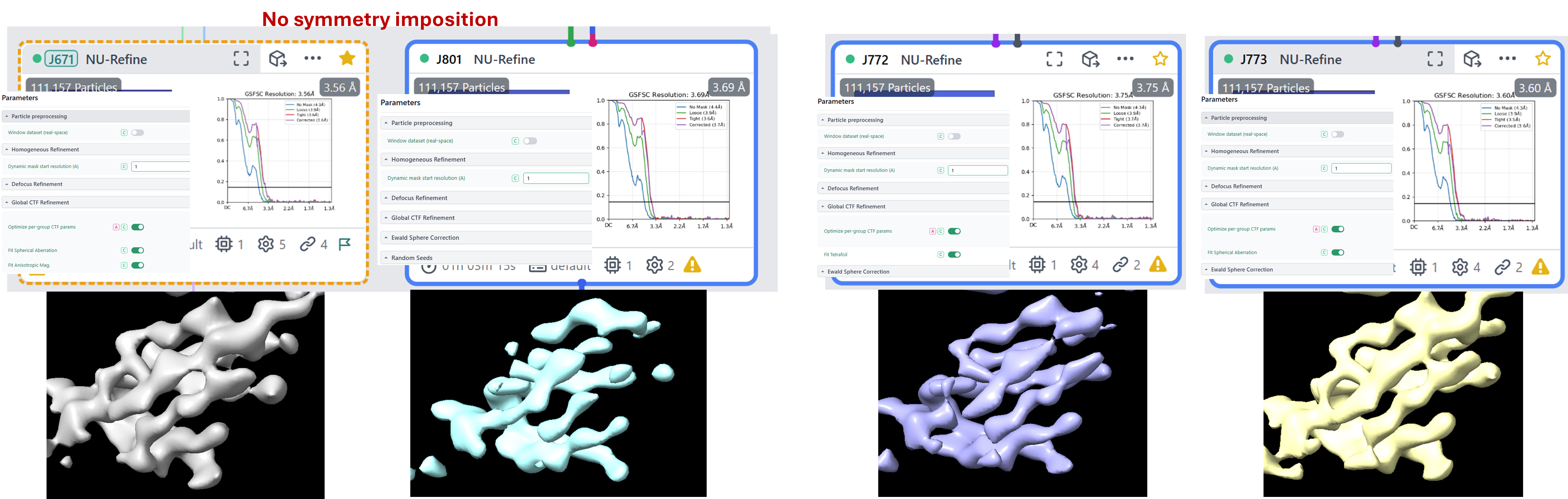
It’s great that you improved the resolution of your refined map by adjusting the parameters!
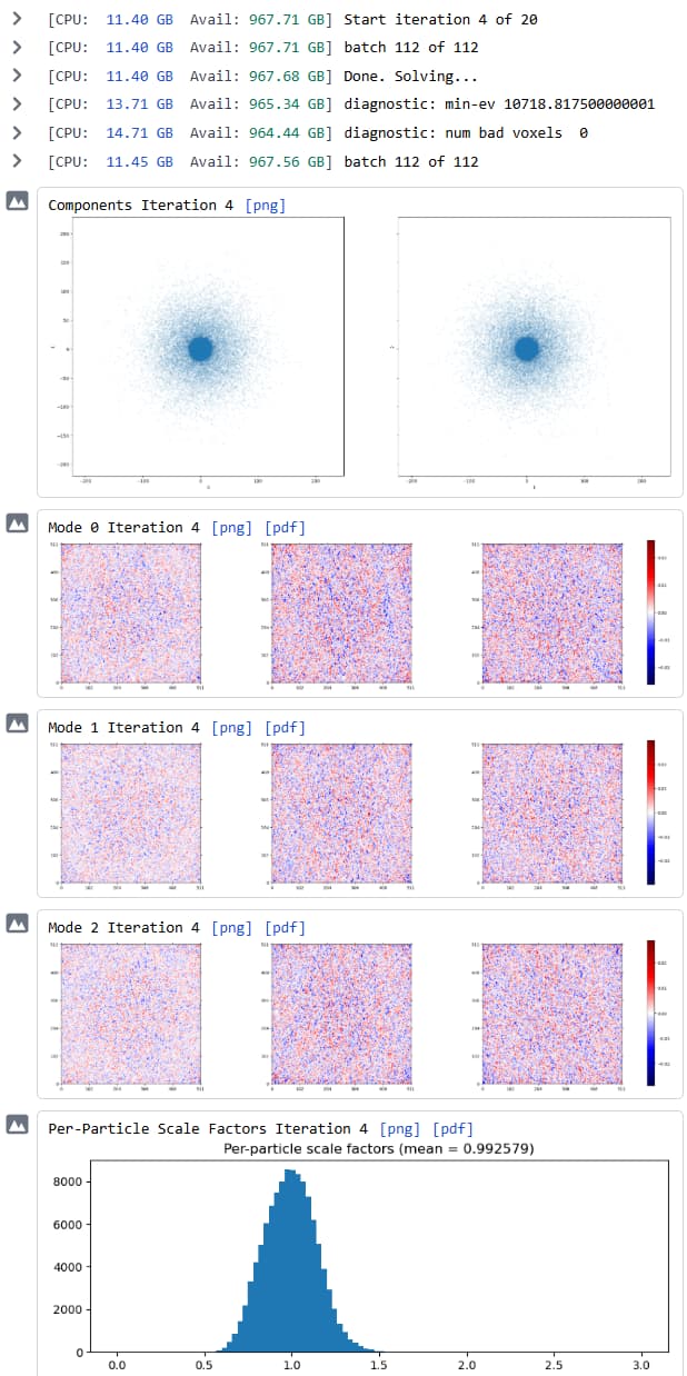
As you effectively disabled masking during NU Refinement by setting Dynamic mask start resolution (A) to 1, in your customised NU Refinement, the output refinement mask will encompass the entire box. Using this mask in 3DVA means that it will not be focussing on the region that contains your target volume, and this could explain the appearance of the job outputs that you show.
To run 3DVA with the particles from your customised NU Refinement in 3DVA, we suggest either using a mask from one of the NU Refinement jobs run with masking, or a custom mask created using Volume Tools.
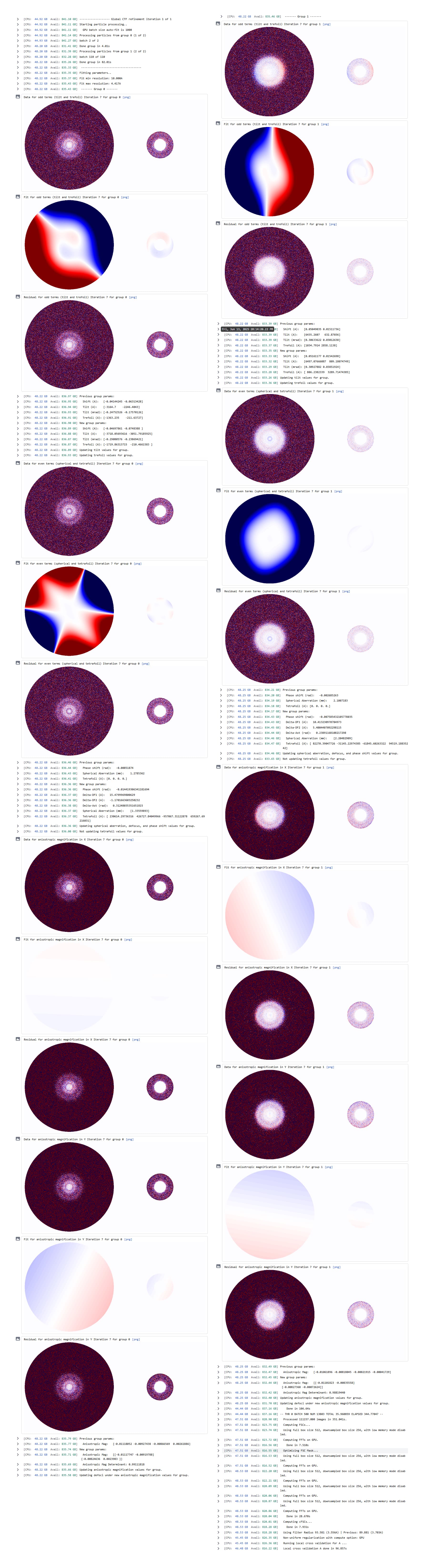
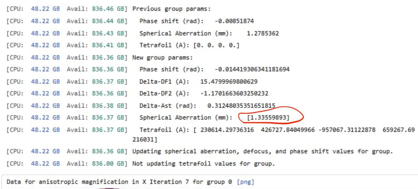
That being said, I also looked at the logs for CTF parameters refinement, but it was a bit harder for me to interpret if anything was off. Here they are:
A lot of this looks like fitting to noise - at this resolution, fitting Cs & tetrafoil is unlikely to be helpful.
How big are these exposure groups, and how did you define them?
Assuming the nominal Cs is 2.7mm (is it?), a refined Cs of 1.35 is extremely unlikely to be correct, or is compensating for a large error in magnification.
I would suggest systematically testing each of these parameters (e.g. just refine tilt/trefoil), rather than refining everything at once.
Yes, the spherical aberration is 2.7 as you stated. These were the particles I got from the live exposure.
Whether these settings improved the map or not, I think yes as at the same threshold I am able to see more density, what do you think?
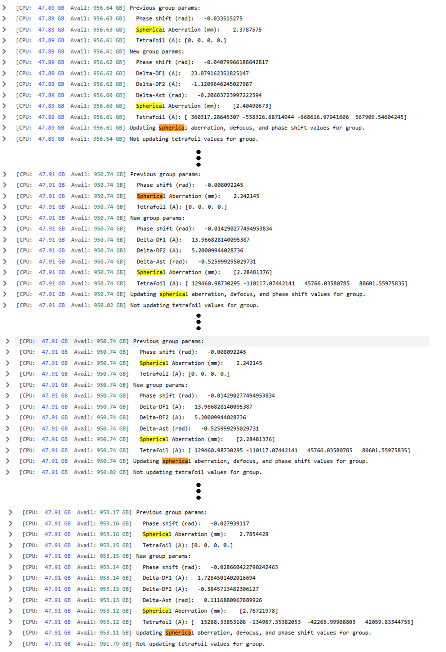
I did some further testing and redid the NU job with the same parameters but on imported movies and hence reprocessed particle set, here are the logs. Does this makes it acceptable now?
You have two different exposure groups. Both have very different refined values for Cs, and both are very far from 2.7, which cannot be real unless they came from different scopes.
Where did the two exposure groups come from? Have you tried treating the two groups separately?
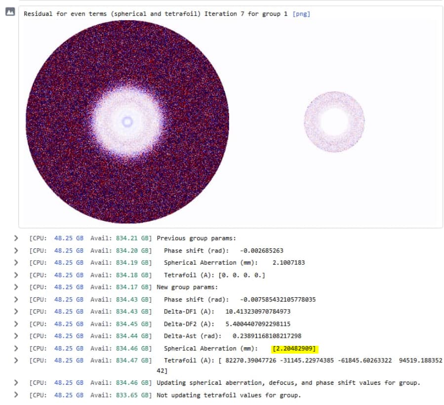
The odd term data plot for group 0 shows no obvious beam tilt; the one for group 1 does show some beam tilt, and perhaps correcting this is helping, I am not sure.
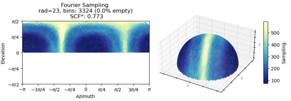
Neither of the two maps shows features consistent with the stated resolution. Perhaps there is some anisotropy present? How does the orientation distribution look?
@olibclarke Yes, you are correct. The scope is the same but dataset collected form separate grids each has a portion (approx 55%) that was collected on a tilted axis and not separated while processing.
The sample exhibits heterogeneity and possible different conformations, which were visible in 3DVA which is why there are regions with less density than others (I screenshotted the area with high difference). Here is another section of the unsharpened maps.
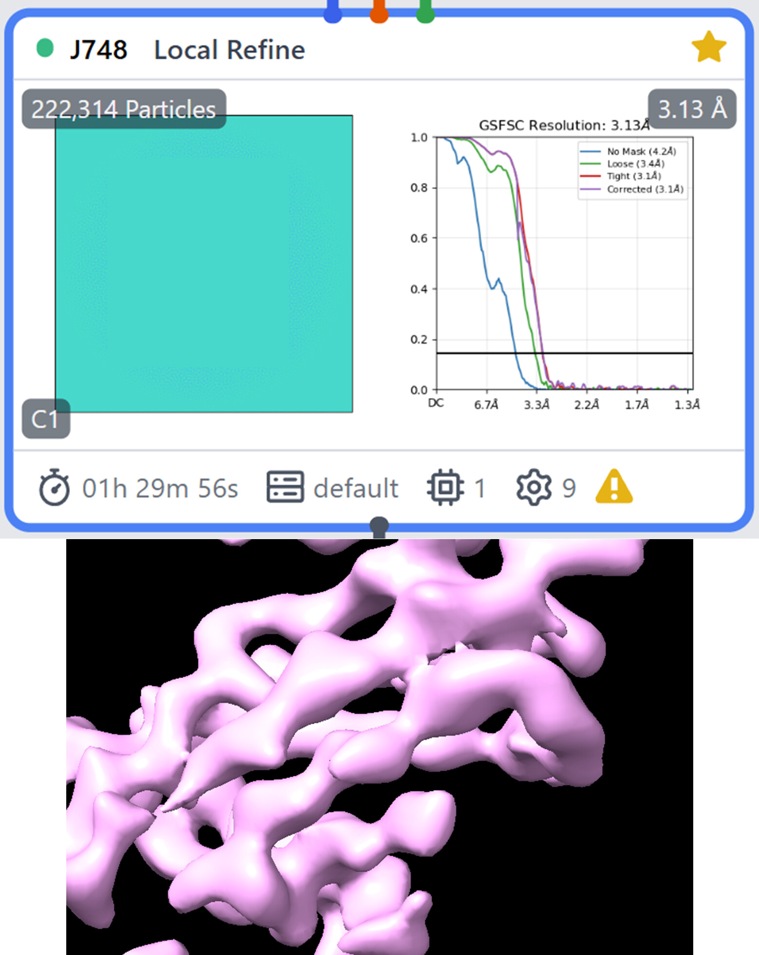
I was able to use symmetry expansion and local refined on the nominal 3.56 angs map to improved resolution of 3.17 angs (nominal) - same section as above.
I would recommend to start with to not refine Cs/tetrafoil/anisomag - you don’t have any evidence for the presence of these aberrations, and refining them will cause more problems than it solves.
I would definitely at least initially treat your tilted & untilted data separately - you can always combine after initial processing.
@olibclarke It would take some time to get that done from the backend. Is there any job in cryoSPARC or any other tool that could allow me to separate the micrographs based on tilt angle? Unfortunately, as per my understanding, the data was collected “mixed”. It was switched halfway-through to tilted (in the same session) and then back to untilted for grid #1 and grid # 2 was half un-tilted and half-tilted within the same session.
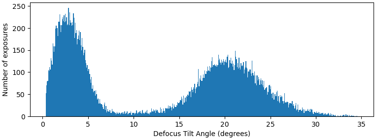
Thanks @olibclarke, for the help and sharing the case study. Although, I have a follow-up question. The data was collected untilted and tilted at 30 degrees only. In the exposure curation job, only one parameter named “defocus tilt angle” was available which I used by giving it a range of tilt angle and the output had a chart as follows:
I was expecting to perhaps see two sharper peaks at 0 degrees and 30 degree. Is this what it is supposed to look like and/or was this the correct parameter in the first place?
Once I have curated the datasets, do I need to redo any motion-correction jobs again or any additional processing that needs to be done or just move along with template picking and onwards?
This is expected - because there are other things that affect the estimated tilt angle, e.g. if there is gold/carbon/contaminants in the frame. In this case I would separate at a tilt angle of maybe 10 degrees and process the two sets separately.
@olibclarke Thanks a lot again. But I still have some confusion. After the curation job, do I restart from the motion correction, or could I move forward to template picking on the curated/split micrographs?
If I need to redo the motion correction and patchCTF, then is there any change in parameters I should consider? If just default parameters, why would it be beneficial to split the dataset in the first place? And at what stage do I combine them?
Also, unless, there is something I do in processing differently, won’t I be left with the same outcome as I currently have?
A separate confusion I have is about your earlier comment, even as you mentioned not to refine Cs/tetrafoil/anisomag, refining them is visibly making a difference in the quality of my map. Isn’t that an indicator that refining them would be beneficial in my case rather than detrimental? Could you please explain more for my understanding?
@olibclarke Thanks a lot again. But I still have some confusion. After the curation job, do I restart from the motion correction, or could I move forward to template picking on the curated/split micrographs?
Just restart from 2D classification. Sometimes combining tilt & non-tilt data doesn’t work so well; and in any case, I would want to classify them independently first before combining.
A separate confusion I have is about your earlier comment, even as you mentioned not to refine Cs/tetrafoil/anisomag, refining them is visibly making a difference in the quality of my map. Isn’t that an indicator that refining them would be beneficial in my case rather than detrimental? Could you please explain more for my understanding?
You are refining tilt, trefoil, tetrafoil, Cs and anisomag all at once. Have you tried them separately? How do you know that specifically refining Cs/tetrafoil/anisomag is making a difference? At this resolution it is very unlikely that refining Cs/tetrafoil will improve your map, and the values that Cs is refining to are not plausible. I would suggest testing systematically, rather than refining them all together. In any case - if your Cs for one group is refining to 1.35mm, something is very wrong, and I would suggest either not refining Cs, or figure out why it is refining so far away from the true value.
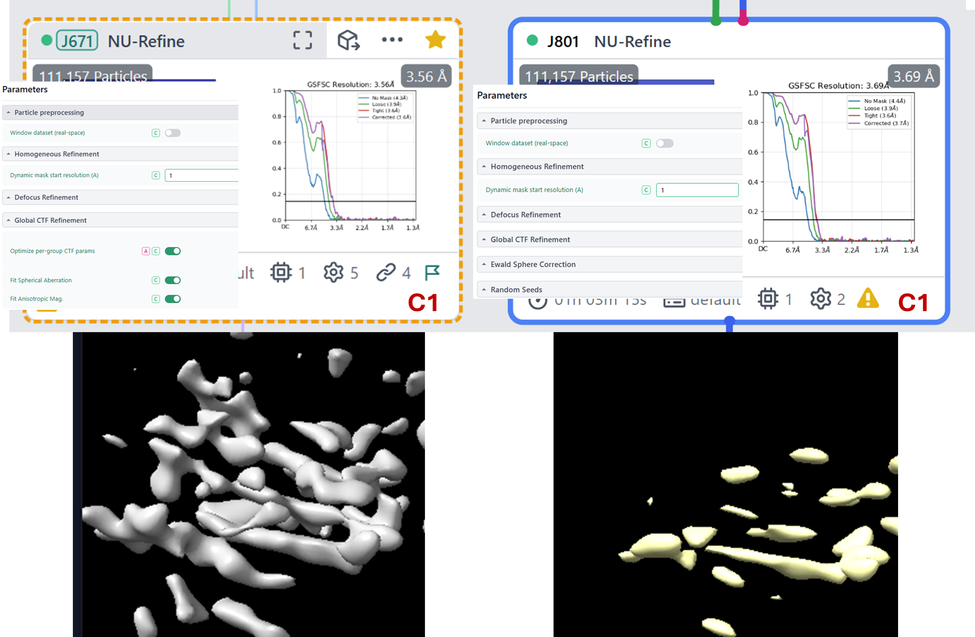
Actually, I am refining only tetrafoil and Cs together, and as you said, I did them separately as well, picture below.
For some reason, Tetra alone makes the map worse, while Cs alone improved the map alot. Then, if I do Tetra + Cs, the resolution and the map improves a lot.
I am trying to figure out what’s going on with those Cs values. I ran another job from a different processing stream and the Cs values were 2.2, 2.1 and 2.6 for three groups. Interestingly, if I run the NU job but with minimize over per-particle scale turned onwhile keeping the other parameters same (for RBMC), the Cs values become way off and sometimes negative. Again thanks a lot for your input and suggestions. I will post if I am able to dig more.
Often Cs refining to weird values indicates that the pixel size is off. Do you have a crystal structure (or in a pinch you can use an alphafold model, but a crystal structure is better) of part of your molecule, that you can use for calibrating maps obtained from the different exposure groups?