Dear Cryosparc Community,
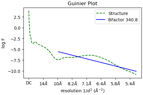
I am working with a sample that has a non-canonical secondary structure that is neither alpha helix or beta sheet. I can generate 2D class averages and ab initial volumes that I believe. However, when I refine it in Hpmogenous refine meant I get volumes which have ridiculously high B-factors as shown with Guinier plot below.
What is even weirder is that in these volumes it looks like cryosparc imposes alpha helix secondary structure on this volume and I can assure that this is almost certainly artifactual especially at the reported ~6 Å resolution.
When use a much more reasonable B-factor (-50) and low-pass filter the structure to ~8 Å I get a volume that I believe based on all prior knowledge we have.
We have some theories that what is going on might be related to a single B-factor being imposed on such a structure and I am currently looking into this some more. If anybody has any insights, I would be curious to know more.
My main question is pertaining to Homogenous refinement itself. When the homogenous refinement moves from intermediate cycle to the next, does it take the sharpened map from the previous cycle or does it use the unsharpened one? My suspicion is that it takes the sharpened map because these artifacts appear to be additive after many iterations. Is this correct? If so, is there anyway in cryoSPARC to work around this and use just the unsharpened maps for refinement? If not, I am even more curious as to what is going on…
Best,
Mark Kreutzberger
Postdoc, Egelman lab
University of Virginia
Hi Mark,
I’m going to answer the question in parts.
The B factor plot you are presenting simply shows the ratio of particle/resolution. A large number means you need a lot of particle to reach this resolution, it doesn’t provide much information. This is unrelated to sharpening B factor.
B-factor sharpening is a way to enhance signal, so one can see side chain better for model building. This only happen at the very last step of Cryo-EM processing - know as post processing. Prior to this, only half map reconstructions are used- thus this does not affect your output. Cryosparc does not know about “secondary structures” and thus will not attempt to reconstruct secondary structures.
The two screen shot you provided are not too helpful, the threshold you are using will determine what you can see.
If you are interested in the algorithm behind. I’d really suggest to take a look at some literatures and tutorial datasets.
1 Like
Cryosparc definitely doesn’t impose any secondary structure.
Have you tried non-uniform refinement, perhaps starting at slightly higher res than the default (say 12-15 Å) if your ab initio map is good? This will often mitigate overfitting. If you are seeing overfitting at mask edges, try running NU-refine without masking (set the resolution to apply dynamic masking to 1Å).
Also, I would try alternative sharpening methods - the default B-factor can sometimes be an overestimate.
I would also consider the possibility that your particle stack still needs some cleaning - this (residual junk in your particle stack) often leads to similar symptoms.
Cheers
Oli
Hi,
Thanks for the response. The final B-factor indicated in the Guinier plot is clearly the B-factor applied to the map_sharp.mrc file at the end of the job. I will read up a bit more on the documentation. Thanks!
Hi Oli,
I understand that cryosparc doesn’t explicitly impose secondary structure. I am more curious if that the application of such a high B-factor has some artifacts that would not be the same in an alpha helical or beta-sheet containing structure. I guess I need to read the literature a bit more!
Your suggestions are interesting on NU-refinement and additional cleaning are interesting. I will give them a shot.
Best,
Mark
1 Like
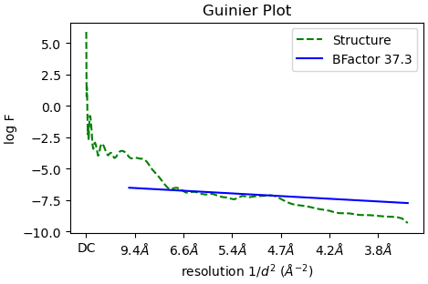
One other thing - your particles are still quite downsampled (looks like Nyquist ~5Å from the Guinier plot?). To get good results in refinement, particularly if you have beta strands you want to resolve, you might want to unbin. Good luck!!
Actually they are not down-sampled. I think that is just where the resolution is filtered. This is from a bacterial flagellar filament solved to 3.7 Å. It stops around there.
Thanks though!
Oh right yes of course - it fits from 10Å to the GS-FSC resolution (this approach does not work great at low resolution by the way which might be part of the problem with your B-factor) - sorry!
Apologies, you are absolutely right. I am the one mixed up with the other B factor.
By applying a large B factor in your case, it’s likely to cause over sharpening, when it’s sharpened beyond resolution actually supports, the feature you are seeing is artificial.
But conclusion is the same, the feature is not something that’s caused by refinement. A good way to analyse the map is to look at the half maps, see how that looks like. That should be a real representation of the refinement.
1 Like
Great! Thanks! I guess my concern was that at the beginning of each iteration two new half maps were generated from the sharpened volume output of the last cycle.
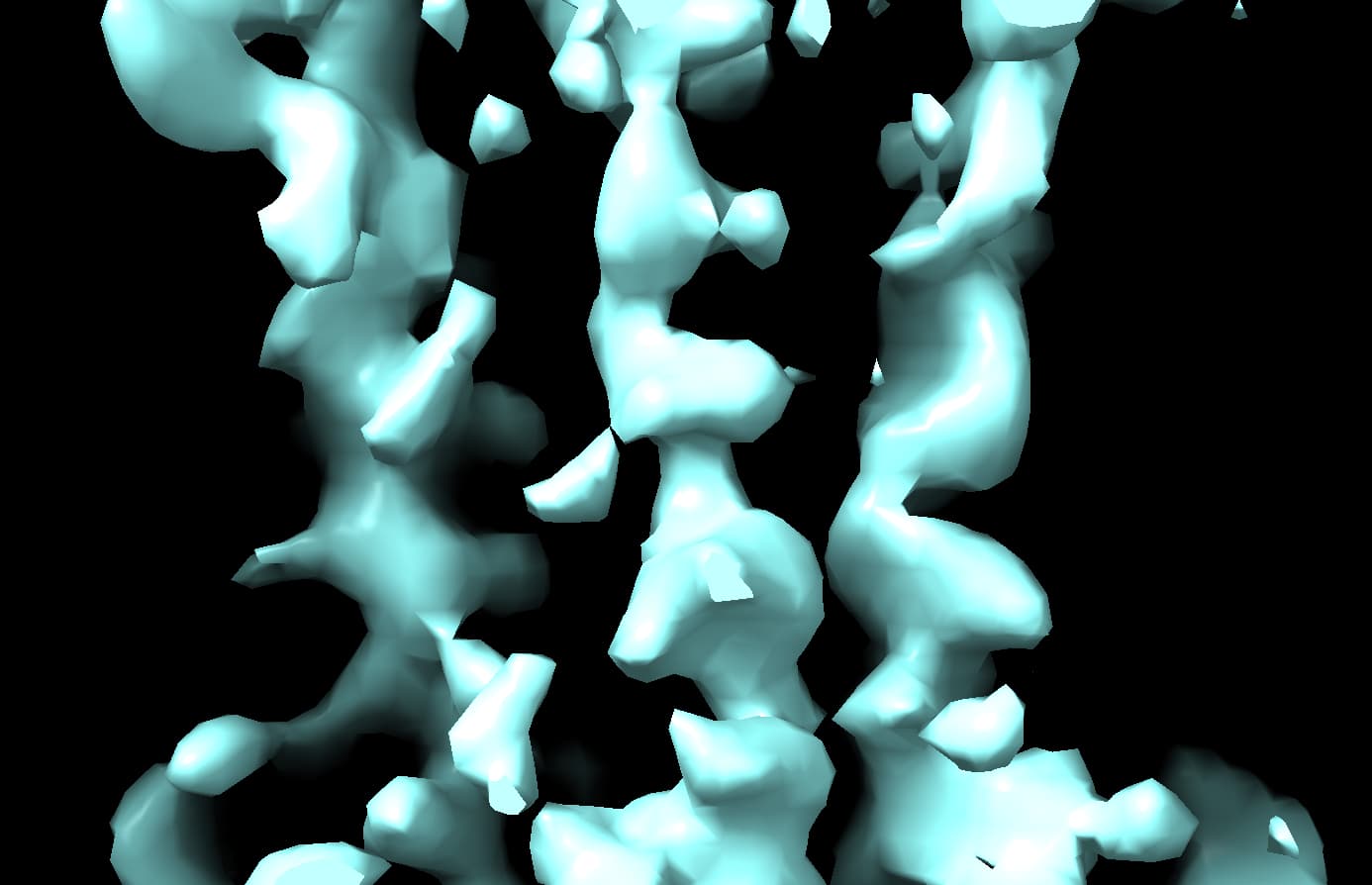
I have a previous related higher resolution structure with a similar B-factor issue and with each cycle the bad density gets worse and worse.
A portion of the structure is good for model building.
But then the rest of the structure just gets worse and worse each cycle. Here is final volume.
For some reason I thought that it might regenerate the half maps after each cycle and then this would compound the issue. But it doesn’t seem like this is happening. I guess what might also be happening is that if the GFSC resolution increases each cycle the bad density would get worse each cycle as well because of overfiltering low-resolution density.
Is this a helical filament?
This one is not. The first structure was.
@MarkKreutzberger
In the so-called gold standard procedure, first two fixed halves of the data are taken. Then at each iteration:
- Particles are aligned to the (masked) reference, the halves are independent between 20-40Å and the refinement limit, which starts at the initial reference resolution
- New half maps are reconstructed (all the particles are used to up 20-40Å, afterwards halves are separate)
- Independent half-map FSC cutoff is used to set the refinement limit for the next iteration
At the end, when the FSC cutoff stops improving
- final half maps are summed
- summed map is filtered by FSC curve
- Guinier analysis used to determine B-factor for sharpening
Note, sharpening does not change FSC curves or normalized cross-correlations, because only Fourier amplitudes are modified.
What you describe - decreasing map quality across iterations - is caused by overfitting of the alignment parameters to spurious high resolution features (noise).
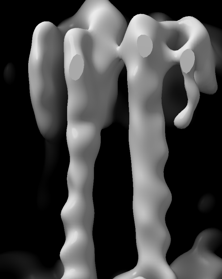
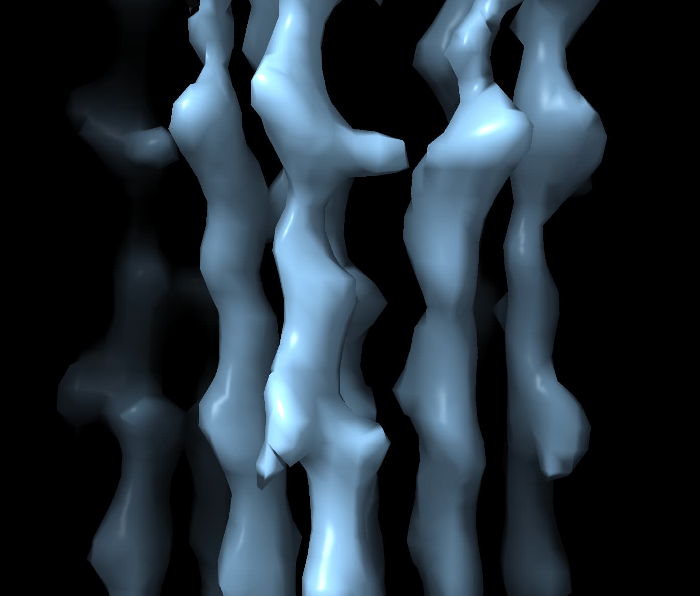
As the streaks from your 2nd image are just part of the structure, I wonder if there is a masking issue. You can disable the automatic mask by setting the “start resolution” for the dynamic masking to something unreasonably high like 1Å. You can also manually limit the refinement resolution, instead of using the FSC to set it automatically. If you make the limit 15Å, what does the map look like? And then if the 15Å one is OK looking, what if you use that for local refinement with a 6Å limit?
1 Like
If it is helical (the first one) then presumably you are using the helical refinement module, not homogeneous refinement?
This one definitely looks like a masking issue to me - use NU-refine and either disable masking or use a very soft mask
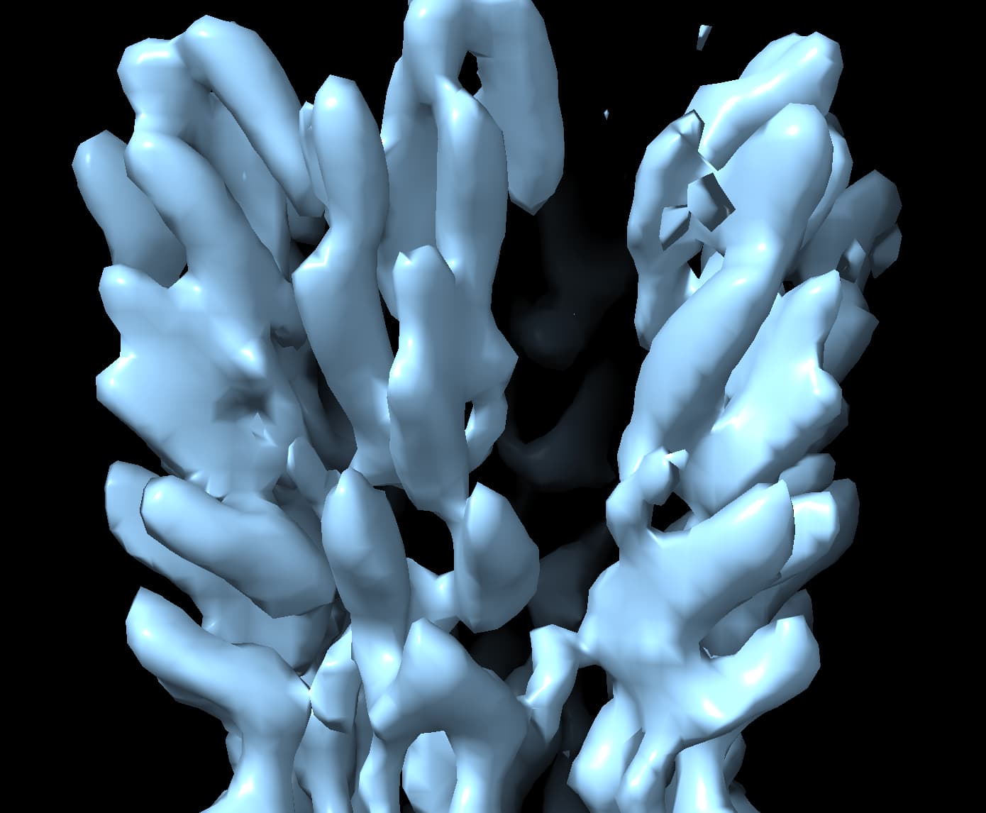
So the first one is a helical filament. But I got a more promising volume from ab initio and homogenous refinement. It’s very much a preliminary structure. I suspect it’s somewhat accurate because I can fit crystal structure into it at 8 Å and it matches with our expectations. Helical refinement yields a similar structure but with a few missing features. There could be a seam or break in its helical symmetry causing this. I don’t yet know…
The second one could very much be a masking issue. It’s also under 100 kDa so that’s another issue. It doesn’t explain why I can get model-worthy density for less than half of the complex. So perhaps it is a masking issue. It also has point group symmetry that may break-down in the worse resolution
region of the complex.
Thanks I will try this. As I said in my most recent post this complex is quite small.
Dan’s advice is particularly salient for small complexes - masking issues tend to be most prevalent there.
If you have point group symmetry (for the single particle one), I would also recommend trying (after fixing masking issues, if present) symmetry relaxation (and, separately, sym expansion followed by 3d classification without alignments), as pseudosymmetry can also cause broken density and is always worth checking for.
It was definitely as masking issue for the smaller particle. It’s not entirely resolved yet but in this case any progress is something. Thanks!
1 Like