Oh! I understand now! By the way, I found that during the picking, some picking piont(small red circle) are not at the center of the particles. In this case, if two different particles are close to each other and picking point are near the boundary of the particle, so that the distance between them is less than 20Å. One of them will be removed. Will this situation happen?
I understand now~ Really appreciate your kind help!
Translations during 2D classification may re-centre particles if the pick is slightly off. One pick close to two particles will just extract one box, not two.
Optimising the minimum and maximum particle diameter, and whether or not to use circular, ring or elliptical “blob” will impact the blob picking results (as will distance between picks and maximum picks).
If you re-pick with templates (one “side”, one “top” view is enough) particles should be centred much better.
There is a lot of effort being put into improving picking algorithms (speed, accuracy) so different programs/methods will give you different results.
This is exactly the information I don’t know~ Thanks for your guidance. It means a lot to me!
When I think of FSCs which characterise duplicate picks, I think of something like this:
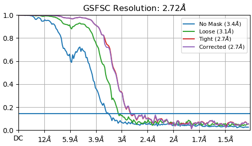
Where at no point does the FSC fall to zero (flatlines around 0.05 - 0.08).
The above FSC is from a total of 9,224 particles from 20 micrographs of the T20S dataset, picked with default parameters except for a Min. separation distance of 0.4 - and it is really, really obvious in the diagnostic output that it is double picking particles.
A good FSC looks like this:
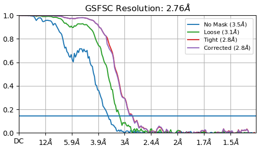
And actually contains more particles (9,548) than the bad reconstruction, as the picks were better and resulting high quality classes contained more particles. I used a Min. separation distance of 1 for this result, but changed the blob shape from circular to elliptical.
There are lots more things to play with in the settings and the online instructions (manual, tutorials) are important reading. ![]()
Yes.-I also tried picking with Min. separation distance of 0.1, which obviously has a lot of duplicates. And the FSC curve is similar than yours which showed platform and cannot reach 0. This situation can be easily understood. But what really confused me is my strange FSC curve. It contains not small percentage of dupilcates but can reach 0. Maybe that because there are particles which don’t have duplicates exist in my set.
Hi all,
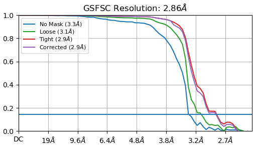
My particle size is 110 A. I used a box of 220 pix. At that stage the FSC curve looks fine for me :
But after extracting my particle to a bigger box size (330 pix) to catch the delocalized signal I end up with this kind of curve.
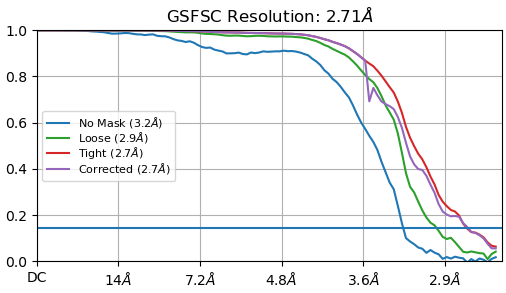
Can someone explain me why the curve doesn’t drop to 0 when I use the big box ?
Cheers,
Kevin
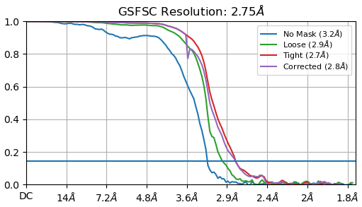
edit: I think this happened because I rescaled my box size (330 → 230 pix). Indeed the curve is really nicer without rescaling. Thoughts ? Moreover, what this peak on the corrected curve means ?
FSCs 1 and 3 look OK. FSC 2 looks like an FSC which does not drop to zero because of binning (which changes the Nyquist limit).
Use the bigger box and don’t rescale. ![]()
Hey @rbs_sci, thank you for your response! That’s exactly what I’ve done and it corresponds to FSC 3 ![]()
I’m still wondering about the bump observed in the corrected curve when it starts to drop
That’s an artefact from the automasking. It’s a little too tight and the dip is the result.
With high symmetry (D7 in this case) and crowded particles / large boxes, you can also get duplicate particle-like FSC effects. Maybe that’s what’s going on here, I’ve seen it happen with T20S datasets before. I wonder if the automask is picking up things outside the particle perhaps?
The purpose of automask is to define a mask that encompasses the particles while excluding the surrounding areas, such as the background and noise. But the extent to which it covers or excludes neighboring regions can be adjusted.To achieve precise control over mask creation and ensure that it covers only particles, it’s essential to review and adjust the settings within CryoSPARC during the automask generation process. This may include thresholding, erosion, and dilation parameters to fine-tune the mask as needed.