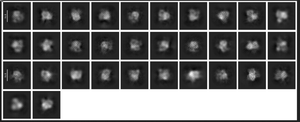
I was surprised by how the 2D classes look like. I imported/motion-corrected/CTF estimated all movies, and blob picked/extracted the particles. They are, as shown in the picture bellow, granular, with repeating circles that are overlaying with the actual shape of the particle:
In this specific case, I don’t think the ice is the cause (but correct me if I’m wrong). Do you know what might be the problem ? Alignment ? Bad picking ? Any clue is welcome.
Total count is about more than 1 million, and each class (at least the first line) is about 50 000 to 20 000 particles. I’m just surprised because the ice did not look that thick during the collection and on the micrograph that I attached to my initial post.
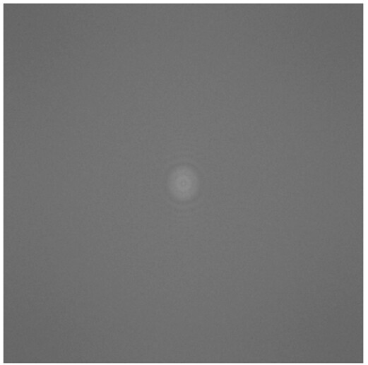
I second the request for FFT/power spectrum for that image.
My suspicion is that when you check the micrographs the particles from the nicer class (third row, second column from the right) it will be a micrograph with visibly better particle visualisation.
How do you collect? If using EPU, it reports for each exposure the dose-on-sensor in a very user friendly way. This is useful, as it allows you to calculate (a) total loss and (with some estimation, b) ice thickness. At least in my experience, “thin” ice is usually 7-10% loss of total dose. If using carbon film support, bump that up a little more. Thicker ice is usually 20-25% total loss, which can be extremely troublesome for small particles. More than 30% loss and unless you’re working with some exotic samples requiring very thick ice, I’d suggest trying to find a thinner area or try adjusting your blotting conditions.
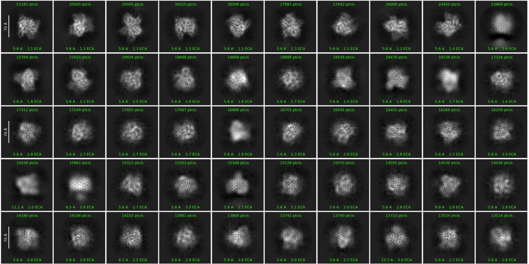
I think you were right about the ice thickness, so definitely the best improvement will be this. However, I denoised the micrographs and did a template picking on the denoised micrographes, based on manual picked particles, and it did improve a lot the 2D classes:
So it looks like rather than preventing a good 2D classification, ice was essentially making the particle picking difficult. I am now facing another problem at the ab-initio / 3D classification / homo refine steps, because the particles seems highly heterogeneous, but I think I will not obtain any better 2D classes with this dataset.
Those classes are a lot better, but still show signs of thick ice causing trouble. More cleaning could help a little (particularly if, as you say, it’s extremely heterogeneous) but if you have the option (sometimes there isn’t…) trying for thinner ice would probably help more.
I have a last question: could the ice thickness be even more important when the size of particle is small ? I solved a lot of structures of 500 - 700 kDa protein complexes in the past, and it seemed to me that with a similar thickness, the results were a lot better. In the present case, the protein is approx. 150 kDa, which is still ok for cryo-EM, but is the ice thickness more critical when the protein size is decreasing ?
You’re right - as particle size decreases, ice thickness plays an increasing role. Think about relative signal - if your ice is 150nm thick, and your particle 70nm, at the point of a particle, how much of the signal is particle and how much is vitreous buffer? Whereas if ice is 150nm and your particle 10nm, the ratio of particle signal to background signal has decreased a lot. An (over?)simplification, but should give you the idea.
edit: Numbers chosen for illustrative purposes, not for any real reason (just to be clear…)
@daniel.s.d.larsson Calling it a technique might be a little generous! Just a rough guide - and little more than an anecdote based on acquiring a lot of different samples on a Krios with a Selectris-X, observing dose-on-camera-through-sample versus dose-on-camera-through-vacuum and some (very) rough correlation to dataset behaviour. As I mention, it is sample dependent.
I’ll check out the papers you suggested - I’ve seen the plasmon imaging one (which I should re-read), but the other two I’d missed (although in the case of Rice et al. it’s because I can’t access it) .
I’d be interested in your results if you do any tests of this yourself!
Yeah, technique is perhaps not the right word (I’m not a native English speaker).
I love these type of anecdotal observations, that is why I asked for more details. It is not obvious that the same numbers would apply for e.g. a Glacios without an energy filter. If you do not have an energy filter, it is also possible to use a small objective aperture (which will cut high-angle scattering) for the same purpose. Without energy filter and objective aperture, the transmission loss will be much less, so you would underestimate the ice thickness. 200 kV has higher scattering cross-section than 300 kV, so with a Glacios, you would instead overestimate the ice thickness with the same values.
Here is a paper with an associated software for automatically estimating the ice thickness using the objective aperture method. Brown & Hanssen. Comm. Biol.5, 817 (2022)
Has anyone used CTFFIND5 to determine ice thickness? It’s a bit inconvenient for screening because you need to record movies and motion-correct them before CTFFIND5 can give you anything meaningful. But it’s still a bit less overhead than importing into a CryoSPARC project and checking the “relative ice thickness”. Also, CTFFIND5 apparently provides an estimate of the absolute thickness, but from the paper it seems like it won’t work reliably (at all?) if the true thickness is out of its search range of 50-400 nm.
I’ve only tested the utility of the tilt/defocus estimation in CTFFIND5 (well, and the 16-bit MRC support). But not looked further. Thanks for reminding me about it…!