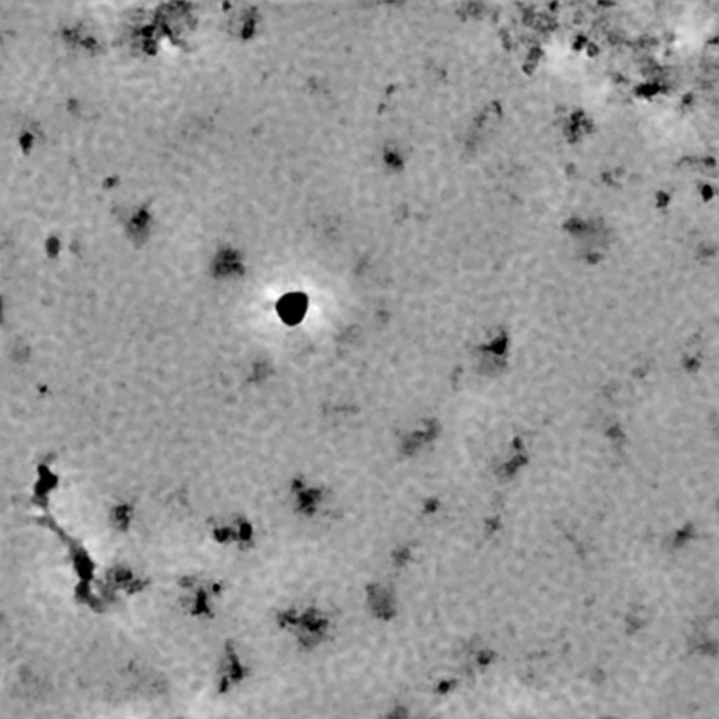
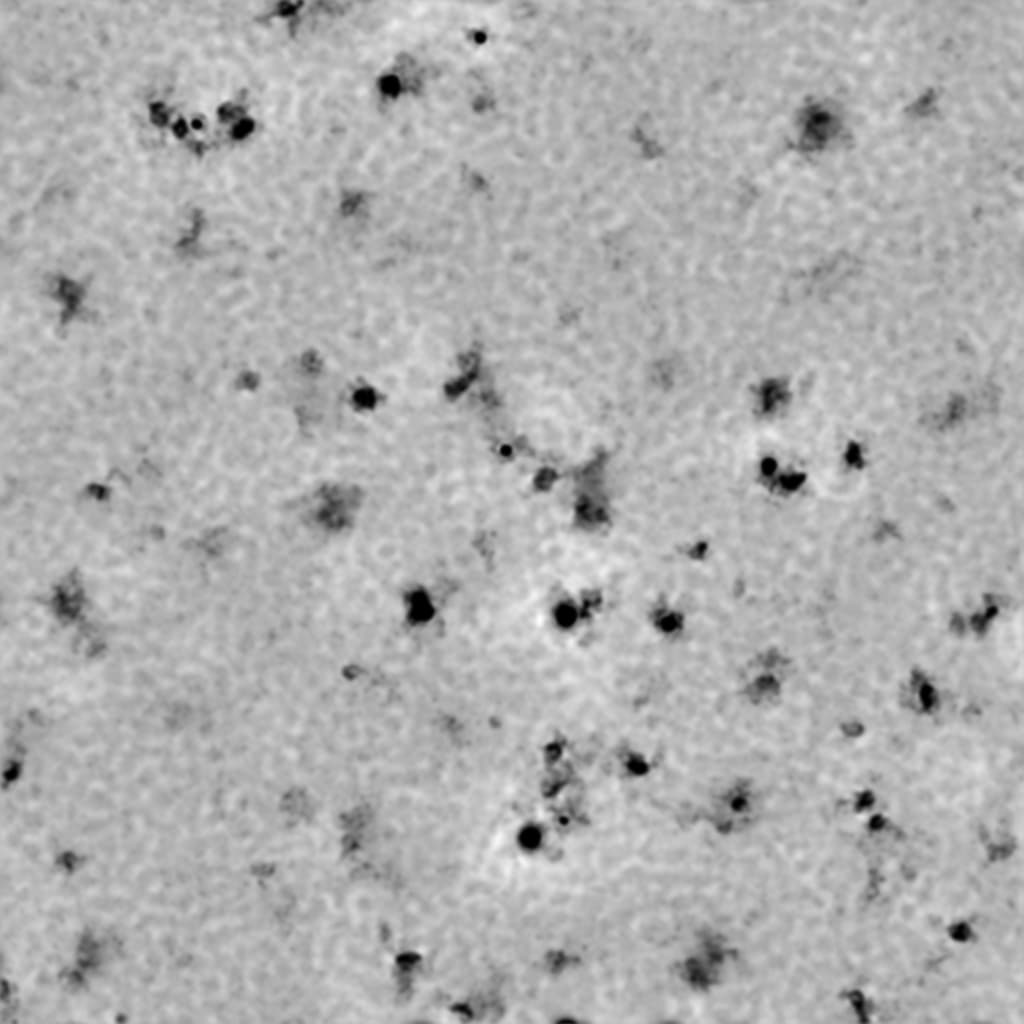
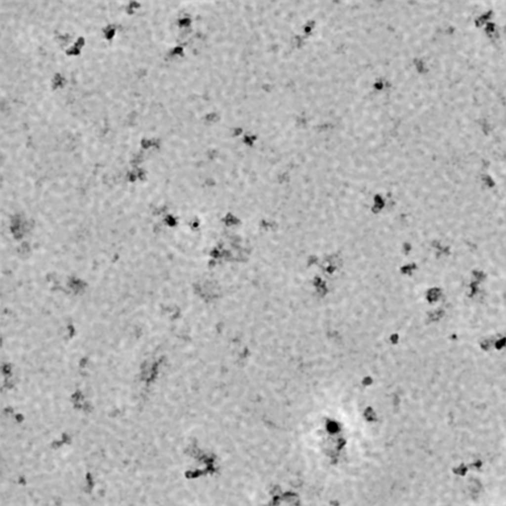
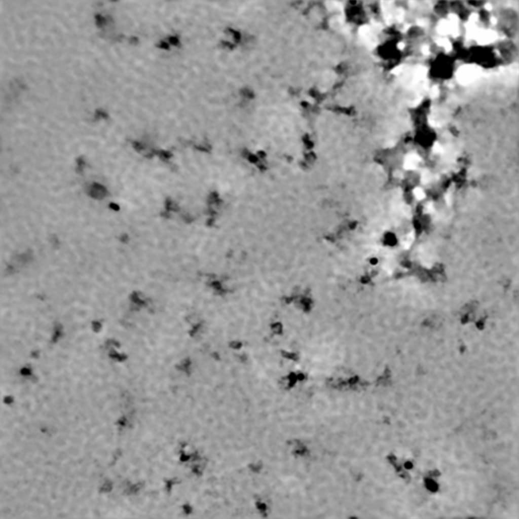
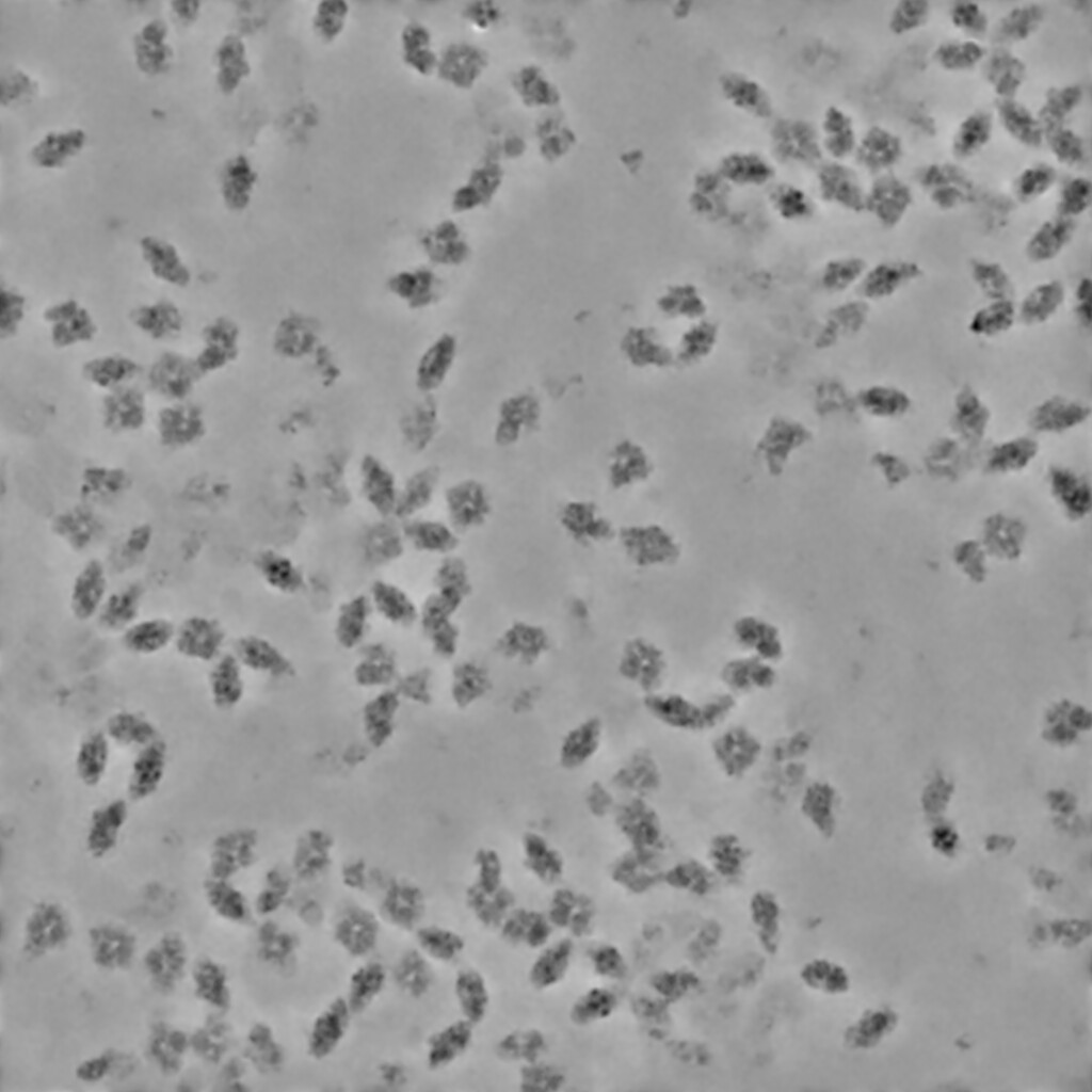
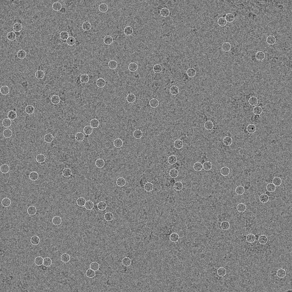
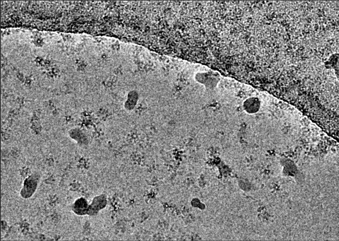
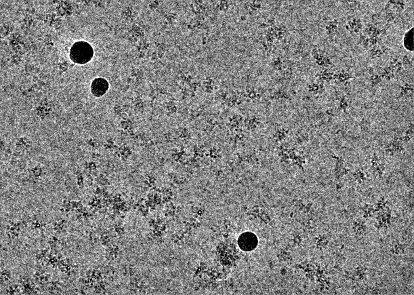
I collected data on a complex that should be a tetramer with a MW of 2x (70+30) kDa, but it seems the particles have high heterogeneity. I am new to cryo-SPA, so would greatly appreciate guidance in evaluating the data to decide if I should spend more time on this. Here are a few representative denoised micrographs. I have already tried blob picker and template picker, but none gives anything that makes sense. Now I plan to first manual pick to train Topaz. But I am not sure it is worth pursuing.
@xyao what is actually picked ? Even with donoised micrographs, the particles seem very contrasty/dark. It seems a lot could be at the air-water interface and there are some spots of aggregation. Do any of the 2D classes show high resolution features ?
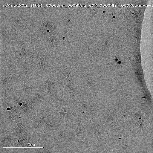
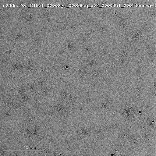
(edits) - what is that background pattern ? Is this continuous carbon or GO ? I’d be willing to bet that is not holey/unsupported. Just wondering since there could be some picks outside of the holes, you defiantly do not want those particles.
I agree with @Mark-A-Nakasone, although the background might be bad ice as well. Not quite so worried about the high contrast particles, that can happen if the training data contains a lot of micrographs with fairly dirty ice. Even the best ice I’ve seen recently can have oddly dark bits of particles… e.g.:
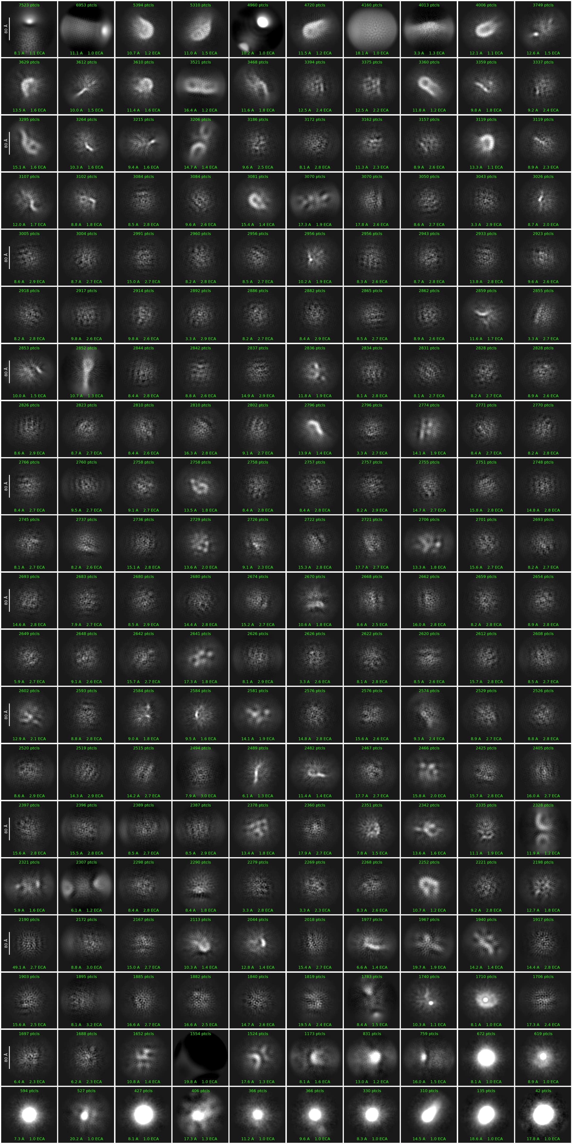
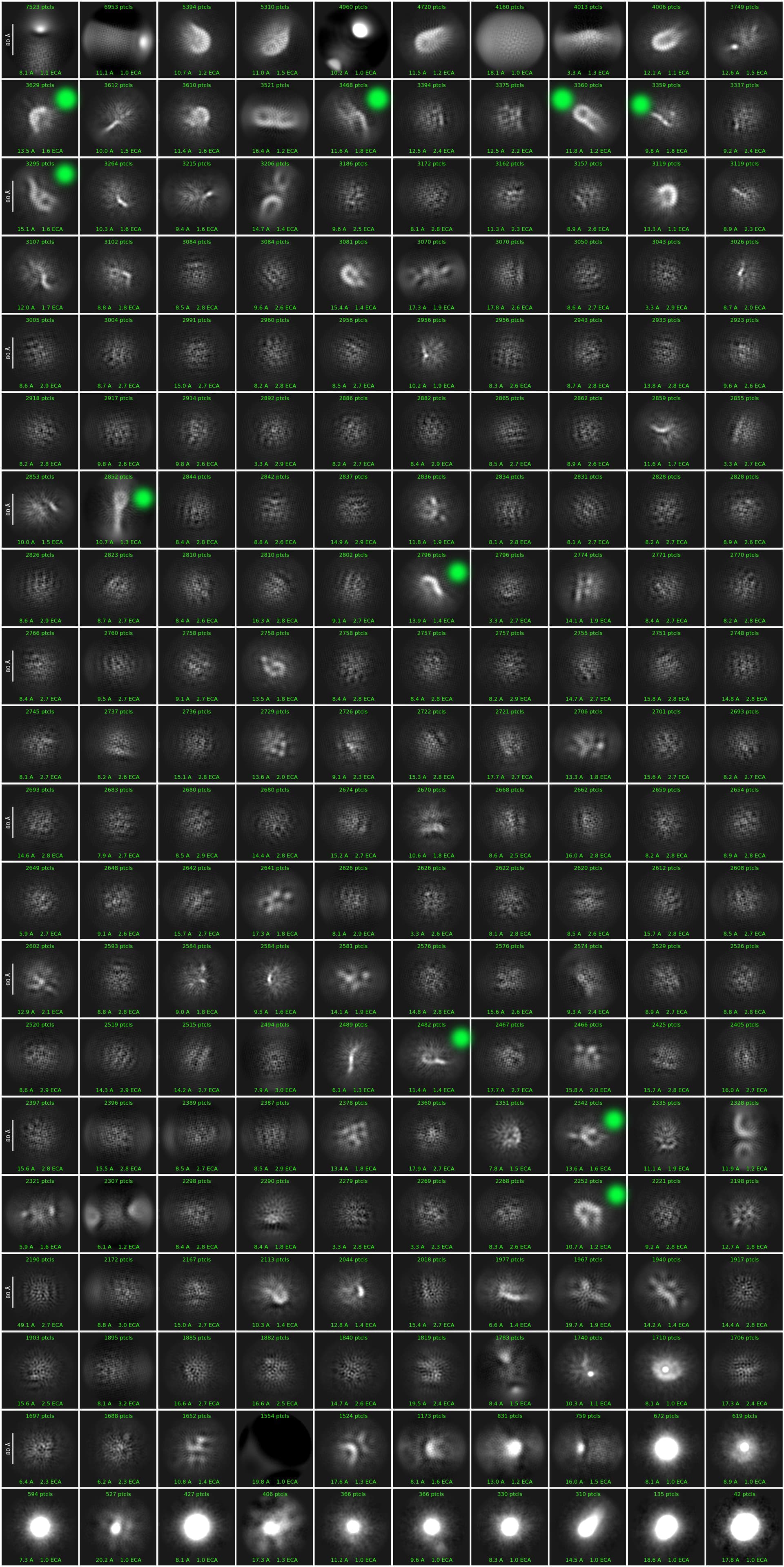
Thanks for the reply. I will attach a few pictures in the next reply with picks and 2D classes. I do not see any high resolution features in the 2D classes.
“what is that background pattern ?”
I don’t have my notes with me at home, but I used either Quantifoil 1.2/1.3 or UltrAufoil 1.2/1.3. I think this is the latter.
That was my initial concern, @rbs_sci has good points.
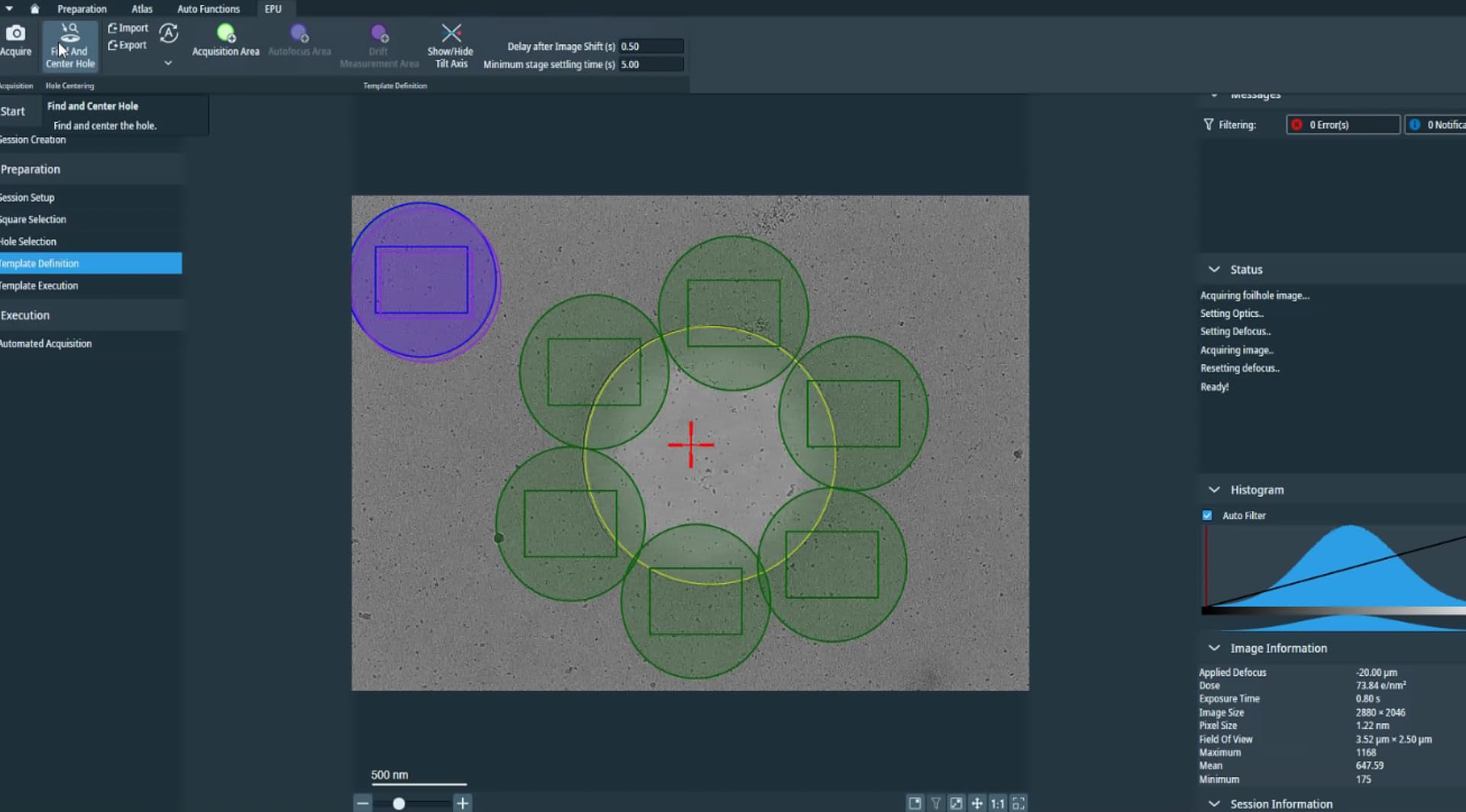
I would check the template from EPU (acquisition area) and if possible if the calibrate image shifts was done correctly - some hints in the .xml meta data.
If, and only if there are micrographs in the hole, I would try blob pick on regular (not denosied micrographs) then use Inspect Picks job, change the levels and it is easy to get things off the carbon between the holes.
As @rbs_sci and others would agree, you simply cannot get a good data set from particles picked/extracted from this support carbon - they have to be in the hole. Note, we do love some support carbon in the micrograph and it can help with focus, CTF, and estimating other alignments - but no particles should be coming from there. Working on UltrAuFoil (all gold) would limit this issue and reduce beam induced motion. I would go have a serious discussion with whoever collected your data. EPU and Serial EM can both miss the hole if things are not set up correctly, and there is no way to correct this acquisition problem at the processing stage.
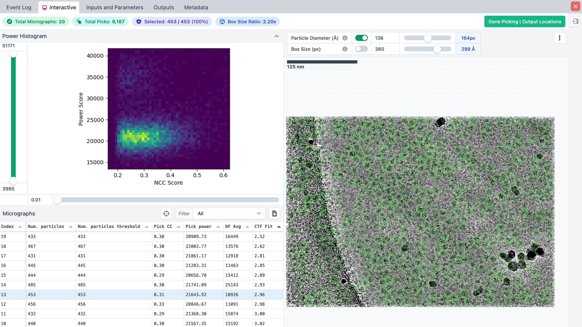
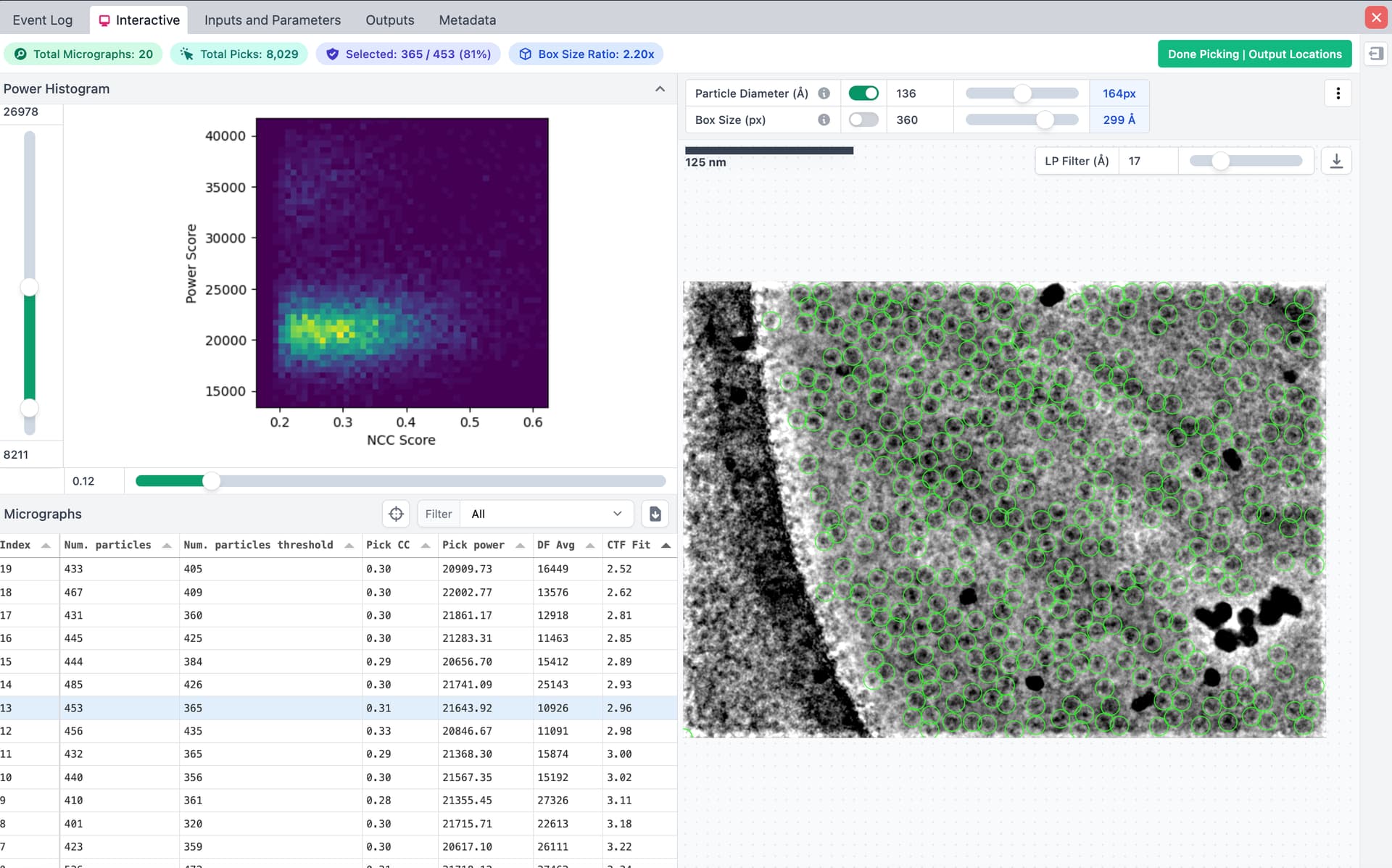
@xyao some picks are clearly on aggregates and contain 2x molecules - 95% junk overall which can happen with the 1st round of blob picking. If they are not outside the hole, the attached 2Ds could be selected and reconstructed (ab initio with 3-4 classes) then see what comes out, does the volume appear like your complex ? Also not a lot of particles per micrograph, best to improve this sample.
Can re-do 2D with these or use a subset of 1-4k particles for training Topaz. I would not train Topaz on the stuff between holes, TOPAZ can train when you give it so if it all particles picked in the hole it will get those, but if enough particles for training come from the support carbon those will be picked by the TOPAZ model.
Agreed. Although given I find it fun to see how far I can push this, it pains me a little to say it.
Beam catching carbon edge is safest. Try to catch the edge of the hole with the beam edge if possible - this can be a careful balancing act to keep the beam tight enough for optimising multiple shots, keeping dose optimal for detector and acquisition speed, etc. It will help with charging/motion. But keep the detector square off the carbon!
When experimenting, I’ve managed 38 exposures per hole (R2/1 at very high mag) (42 if I squeeze things in a bit tighter than I would recommend) but similarly experience has taught me that shots in the middle are usually wasted shots from charging and excessive particle motion. So no middle shots.
Or, alternatively, if using a Falcon 4(i) or K3, do one shot per hole, crank the magnification down until you’re nearly catching carbon on the corners and use super resolution. If particle count is a problem, do some basic area comparisons: what gets you more area acquired? One shot at 2 Å/pixel (physical Nyquist), or five shots at 0.57 Å/pixel? Don’t forget, with CryoSPARC, a box off the edge is a particle not extracted.
One shot in the centre of a hole is a touch more forgiving if EPU mis-centres a stage move (it happens, ice conditions are a common cause of the hole centring algorithm getting confused) than five shots around the edges. It’ll cost you some storage space, but tweak the dose rate and you can get double the area in the same total per-hole exposure time. For me, doing this results in micrograph movies approximately 1.5-2.5GB is size (depending on total dose), with double the acquired area of the multiple-shot route. Five higher mag shots come out to roughly the same storage capacity used (closer to 1.5GB…) and take more space when motion corrected, too (5x 128MB for 8K 16-bit MRC vs 128MB)… Especially since most samples aren’t aiming for <2Å, it can be a good strategy if particle hunting is a problem. Admittedly, for small proteins it’s a bit trickier.
Thanks for the reply!
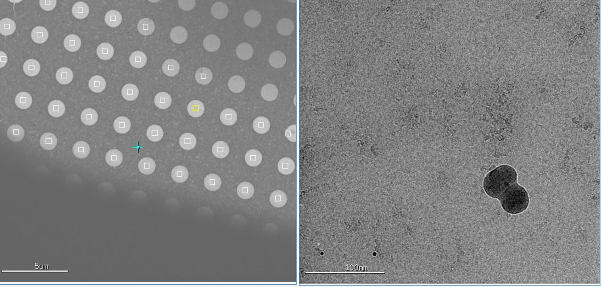
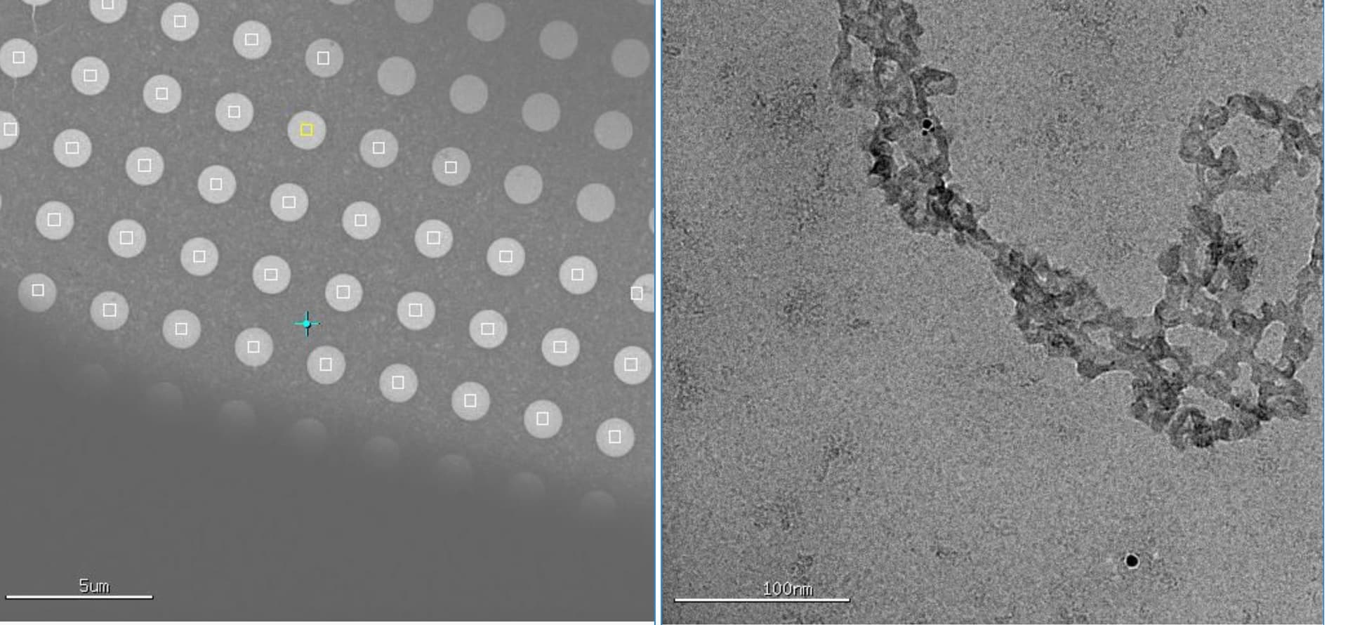
I don’t understand why the shots are on carbon film, the area for data collection are manually selected on holes, as far as I remember (I was watching during the setup). Also, what are the features I should look for to know the micrograph is on carbon? I attached a couple screen shots below shows which hole is collected (left) and the image (right). I think both have big ice contamination, let me know if this is not what you are asking and I will find more images.
Thanks a lot for the details. Now I understand why the micrograph I posted are from carbon even though I saw only holes are selected. I would need to look over the data and figure out if there are any data collected on holes. I will keep this in mind for future data collections. I did check the images shortly after data collection started, unfortunately I didn’t know enough to spot the problem. Lesson learned!
Also, great tips on limiting number of shots per hole! I was not aware of this potential problem.
Thank you very much for the detailed tips. A lot to digest here.
BTW, regarding my reply to your last reply (I am learning how to use this discussion board ), I learned from Mark’s comment why I was getting images off carbon support.
thank you for the info @xyao, that is some serial-EM then. seems the holes are close to the grid bars /edge of the grid square. The acquisition area also appears to be in the center of the hole, for single shot. when you were screening, were the particles better near the edge or the center of the hole ? some ice, but some aggregation ? cubic is usually not electron transparent, but many aggregates are. very strange how your first micrographs are missing the hole ~90%+ support carbon.
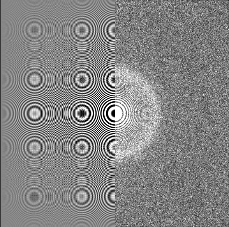
Position of hole edge is an immediate giveaway if positioned in-frame. Otherwise, you will usually see a mottled effect in the image, or significantly higher protein concentration, sometimes pushing into aggregate territory but not always. If ice is thin on the carbon, sometimes you can see distortion of your particles (if large/symmetric) but again, not always. Otherwise, very strong Thon rings in the power spectrum is an immediate red flag for being on carbon. I’ll see if I can find an example or two…
edit: Examples:
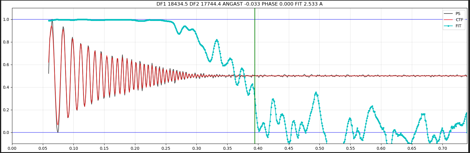
Micrographs with carbon often look like this:
Where the CTF is significantly stronger and low frequences and decays fast and usually fairly evenly.
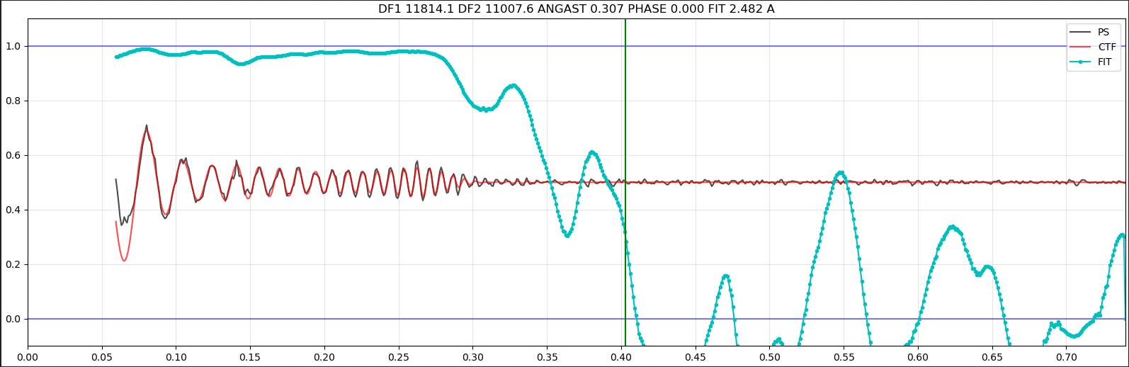
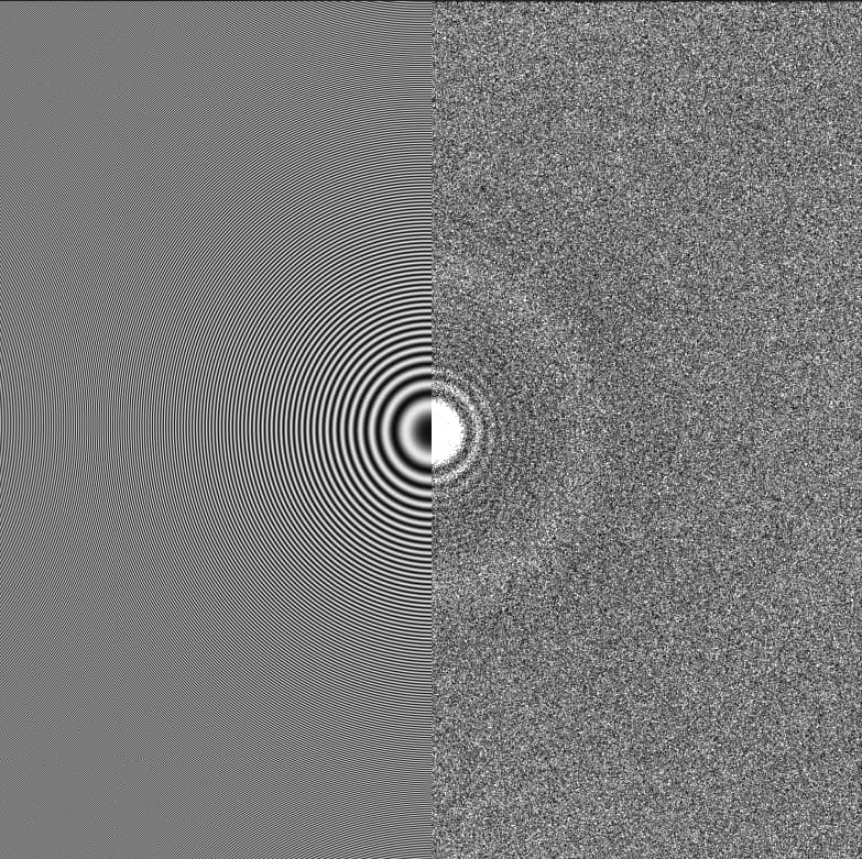
While ice ones can have just as good estimated resolutions (or better - estimated resolution is not a good metric for “carbon/not-carbon”, but micrographs with carbon in are usually high-fit-accuracy because the Thon rings are strong!), but the oscillations are not as extreme, and do not decay in the same way:
Based on my memory, the particles are better at the edge. Unfortunately I didn’t put down these details on notes and it may or may not be this specific grid. There are ice on some images, which I attributed to my limited freezing skills as I was still learning. There are large aggregations in some images. I didn’t realize proteins on carbon would show more aggregation, which I would definitely keep in mind.
The only explanation would be I made a mistake with dataset when taking the screenshot? The initial ones are from cryosparc, the screenshots are from a viewing app. Unfortunately the data label are cropped off, so I can’t confirm. I didn’t know one can tell carbon vs gold grids based on low mag images, good to know.
Thanks a lot!! This is very helpful. I will have to take another look at the data with these features in mind to have some idea on what portion of the data are collected off carbon.