I have been trying to process multiple datasets whose fit resolution cutoff in cisTEM is between 3-6 angstroms but processing the same on both relion and cryosparc would yield structures of resolution 7-8 angstroms. The micrographs even after gain correction on the fly seems to have wavy pattern. Does the pattern affect have anything to do with this problem.
Would you post an example micrograph? Could be ice, could be beam edge (depending whether microscope has Fringe Free Imaging or not).
Just getting high resolution CTF estimates is not guarantee of high resolution reconstructions…
The K3 CDS mode gain often has a radial pattern. The gain reference might need to be transformed using the movie import options.
Does the pattern have any effect on resolution of the structure?? I can see good signal via the thorn rings during data acquisition corresponding to say about 5 to 6 angstroms.
We are using a K2 detector for data collection. So as per my understanding you want us to collect data which is not gain corrected and then use the gain.mrc file to correct for the gain while the micrographs are being imported for processing?
This is the standard method - you should always do this. The alternatives are to save a copy of the gain in every file, which costs a ton of storage space, or in some software to write out only gain normalized files, which also costs a ton of space (by using a greater bit-depth and by making the data high entropy / incompressible) and limits your ability to correct for a bad gain or certain gain artifacts.
1 Like
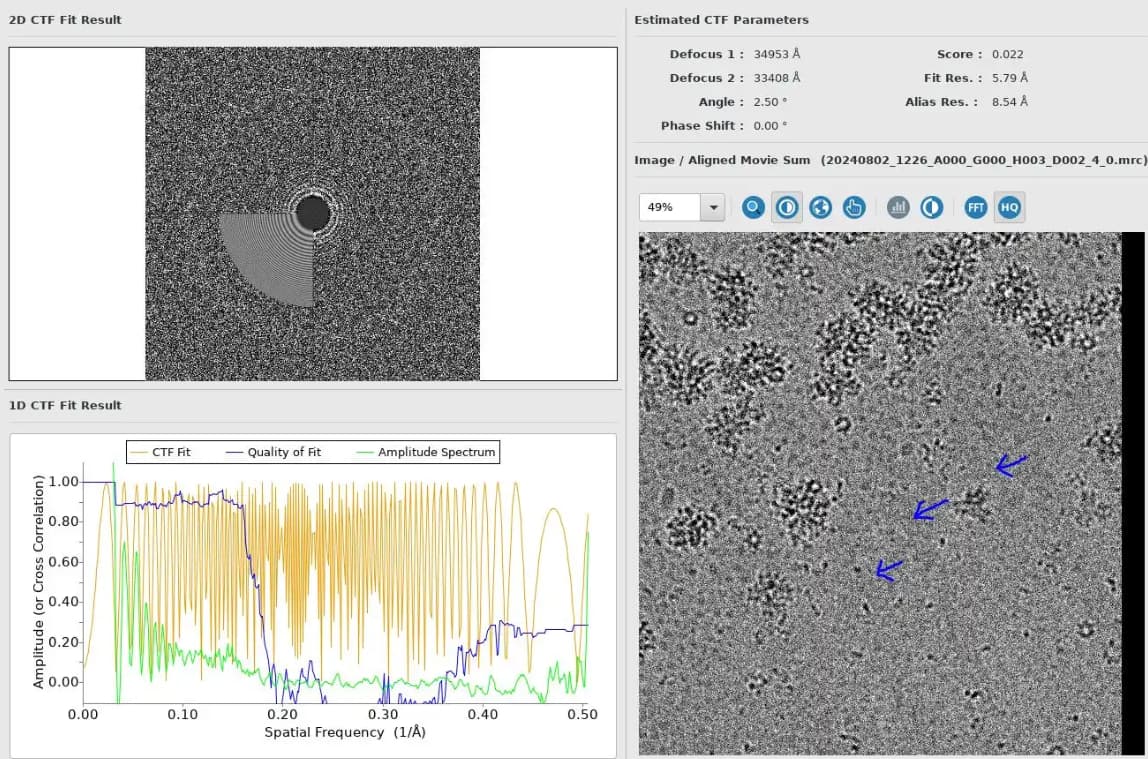
From the image posted, the CTF envelope is pretty severe and rings are visible only to ~10 Å. The defocus is quite high which may be contributing to the poor envelope. The “alias res” reported by cisTEM is also lower than the fit res, which indicates that the CTF oscillations are becoming too rapid to be represented in the power spectrum of the image, before the CTF fit stops correlating with the PS. That is also because the defocus is high, and can probably be corrected by using a larger FFT size.
I don’t see any particular pattern the arrows are pointing out. A gain issue will be the same on every image. If the gain needs to be flipped then there will be mirrored dark and white patterns on either side of whatever axis. There can also be aliasing present just within the small display window in the GUI.
Ah, I can see some slight ripples across the micrograph as a whole but I think that’s just caused by the ice. If It’s not the same on every micrograph it’s not caused by gain being wrong. It’s quite high defocus so that doesn’t help - using a larger FFT size should stop the aliasing impacting so much.
As @DanielAsarnow points out, with the aliasing estimate as high as it is (you ideally want none detected, or higher res than the CTF fit res) you could also try using exhaustive fitting.