Hello everyone,
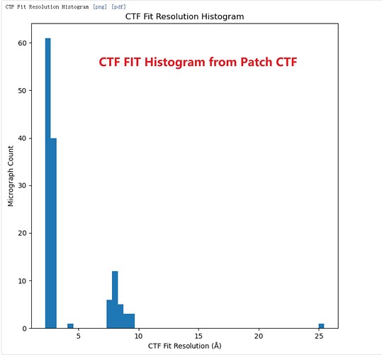
I’ve observed an interesting discrepancy in resolution estimates between Patch CTF and CTFFIND4 . In my dataset, the CTF Fit resolution values cluster into two distinct groups. After running Patch CTF on the movies, I confirmed this bimodal resolution distribution.
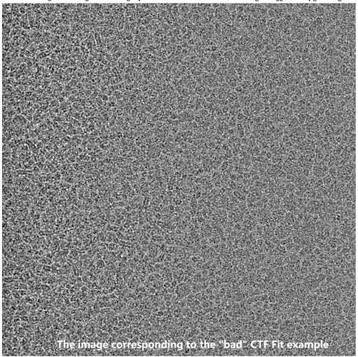
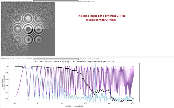
As an example, one movie with a poor Patch CTF resolution estimate (7.72 Å) appeared visually acceptable, yet its 1D defocus search plot from Patch CTF revealed two distinct defocus peaks. Surprisingly, when I reprocessed the same movie (and others in the dataset) using CTFFIND4, all resolution estimates improved to better than 4 Å, including this problematic example.
Has anyone encountered similar inconsistencies between Patch CTF and CTFFIND4? Could differences in algorithms (e.g., 1D vs. 2D fitting, outlier handling, or parameter sensitivity) explain this behavior? Any insights or suggestions would be greatly appreciated!
Thank you for your time!
I’ve seen similar effects - not recently, although that’s because I’m not using CTFFIND in CryoSPARC because 16-bit MRC space saving is more valuable. That said, it can happen both ways; the other way around where CTFFIND will estimate 3-4 Ang, but Patch CTF will estimate <2. Sometimes as with your case CTFFIND does better. I’ve found CTFFIND to be more robust generally for difficult micrographs, particularly when particle concentration is so high, but it does depend on the sample. However, as above, the currently supplied CTFFIND with CryoSPARC does not support 16-bit MRC images, so Patch CTF is the only option if using that.
Bear in mind you will also get different results using different versions of CTFFIND! I used to stick with 4.1.9 (shipped with original cisTEM) for ages because it was the most reliable (for me) until 4.1.14 landed. I also used to avoid Gctf because I’d had several occasions on more marginal data where it reported multiple micrographs with exactly the same defocus, astigmatism and estimated resolution, combined with what I felt were unrealistically high estimated fit resolutions.
Hi rbs_sci, Thank you for your insightful response—it clarified a lot! To confirm, I used CTFFIND4 (v4.1.14) integrated into CryoSPARC for reprocessing. Based on your explanation, I now understand that discrepancies in CTF Fit resolution values can arise from algorithmic differences between software tools.
Would you recommend prioritizing the software that reports better resolution values (e.g., CTFFIND4 in this case) for downstream processing? Or is it acceptable to proceed with the original Patch CTF results (despite their poorer resolution metrics) for both initial CTF estimation and subsequent refinement steps?
I’m particularly curious whether Patch CTF’s bimodal defocus peaks or lower resolution scores might introduce systematic biases in later steps like particle picking or 3D refinement.
Thank you again for your time!
In this case, yes, I would. Just to check, the data isn’t from a tilted stage collection, is it?
I’m also interested in this point - if you have the time, I’d be very interested in hearing what you experience with processing (as similarly as possible) from both CTFFIND estimates and from Patch CTF estimates…! 
Thank you for the follow-up! To clarify, the dataset was not collected using a tilted stage. Instead, the issue arose from the grid itself: we used 1.2/1.3 µm holey grids with oval-shaped holes, which caused EPU (the initial data collection software) to inadvertently target carbon foil regions during large beam-image shifts. Surprisingly, despite this suboptimal setup, the EPU-collected data showed expected normal CTF Fit resolution (around 3 Å) in CryoSPARC Live (using Patch CTF).
To address the excessive carbon foil images, I switched to SerialEM with a refined smaller beam-image shifts (3x3 pattern) to ensure precise targeting of ice-only areas. While this eliminated carbon foil, the Patch CTF results for the SerialEM dataset unexpectedly showed two clustered CTF Fit resolution groups as described above—a pattern absent in CTFFIND4-processed data. Crucially, the “poor” Patch CTF results (e.g., 7.72 Å) did not correlate with beam-image shift direction and appeared randomly distributed.
So, does the presence of carbon foil (as in EPU data) inadvertently “stabilize” Patch CTF’s resolution estimates? For example, carbon might reduce high-frequency noise or provide a stronger signal for Patch CTF’s local fitting, masking potential algorithmic sensitivities? I processed Patch CTF’s “poor-resolution” images and performed particle picking. Extracted particles from these frames still yielded high-quality 2D classes, suggesting the CTF Fit metric alone may not fully reflect downstream utility. Unfortunately, I currently lack full access to the dataset to explore this further (e.g., 3D refinement or per-micrograph resolution filtering), but I plan to revisit this analysis post-publication.


