Good morning, i would like to ask a quick question:
Can I download the skeleton image? I only see the option to download the four images in PNG or PDF, but I don’t know if I can download the skeleton or just the bottom right image, keeping the original size. I’ve gone to the outputs section and downloaded what I could, but I only get “.cs” files.
I’ve also seen in the example images that you can superimpose the red skeleton on the original cell. Can this be done with Cryosparc or is it done manually? (i.e., download the PNG, remove the background, change the color to red, and superimpose it on the image.)
Thank you and sorry for the inconvenience.
Continuing the discussion from Filament tracer export images:
Sorry to bother you again, but I really don’t know how to export the image in the bottom right. It only lets me download the image with four subdivisions, but not a specific one. If it is using Filament’s .cs, I also don’t know how to view the image or export it to .PNG.
It’s probably something very simple or silly, but I’ve been looking for a way to do it for a week and I can’t get the skeleton image at its original size.
Sorry and thanks again.
Dear @aaron.p.p ,
Apologies for the delayed reply. Could you expand on what you are interested in using the image for downstream?
The images displayed in the event log are not present in the outputs of the job (the cs files) nor in the job directory, rather, they are stored in the database. The easiest way to obtain these images is by downloading them from the event log.
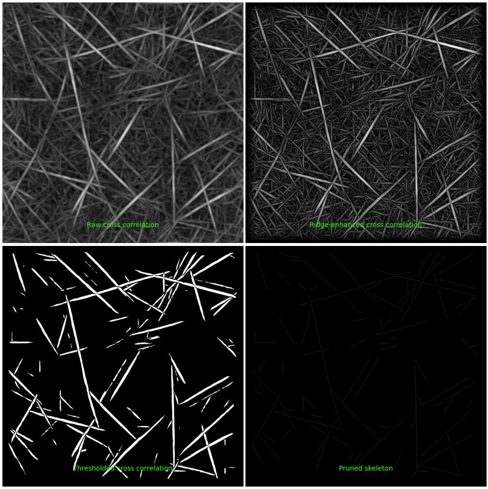
The specific diagnostic image here is saved as an entire image and the four panels are not individually accessible (they are created during the program’s execution, and then merged into this one figure). These plots are also only produced for a given number of micrographs, but this is a parameter of the job that can be adjusted (“Number of micrographs to make diagnostic plots for”). Would it suit your needs to download this image and crop it to the bottom right?
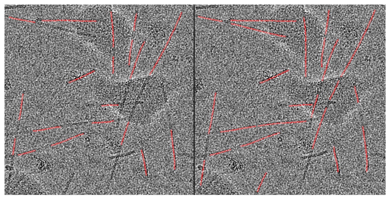
I also noticed that the scale is quite faint for this diagnostic image. Does it also appear faint in the event log, or is it only after downloading and re-uploading the image here that the contrast of the skeleton is compromised? As an alternative, would the red plot of the picks overlaid onto the micrograph suit your needs?
If neither of these are suitable, there would be a way to approximately recreate this plot in a script using cryosparc-tools but will be more effortful compared to the above.
Best,
Michael
Good afternoon.
First of all, don’t worry, I didn’t have to wait that long either. In fact, you responded super fast this time. Thank you very much.
I’m working on a final project on cell segmentation, and my goal is to compare another software with yours. To do this, I want to use the clDice metric, but I need to compare the skeleton generated by cryosparc with a manual one (drawing filaments by hand) to see the accuracy.
For that reason, I need the skeleton image. Although faint, when thresholded, I get a skeleton (array of 0 and 1), but I wanted it to be the same size as the original image and I wanted to remove the green letters that appear below.
For now, I’ve cropped it by hand using Photoshop, but it’s not very “rigorous.”
Regarding the second question, that’s the image I got (along with the generated templates of the filament and the cell with red picks). I don’t mind if the filaments are red, but since I saw on the Filament Tracer page and in some discussion that the filaments were overlapping the cell, I thought it could be downloaded separately or something like this:
So should I do it manually?
Best regards and thank you very much.
Dear @aaron.p.p,
Thanks for clarifying the usage. Based on this, I’d recommend using scripting to extract the information that you need. This would be best done through the cryosparc-tools package. If you aren’t familiar with cryosparc-tools, then it would be best to start with one of the intro (linked above) and then looking through one of the tutorials (the re-center particles one is perhaps most apt).
I can outline what I would do in a script if I wanted to extract the skeleton for this purpose. It’s likely easiest to do this kind of programming in a Jupyter notebook. Note that the raw skeleton itself isn’t saved by the filament tracer, but what is saved is the pick locations along each filament, as well as a unique identifier associated with each filament. Using these, you can reconstruct an image of the filament skeleton.
Let me know if you have some familiarity with Python and if this would be of interest to you, and I will describe which bits of information to extract from the cs files 
Best,
Michael
Thanks again. I wasn’t familiar with cryosparc-tools, but it seems to be what I’m looking for. I do have some knowledge of Python and Jupiter Notebook. If it’s not too much trouble, I’d like to know what you would do in a script if you wanted to extract the skeleton. If you can’t or are too busy, I’ll investigate. At least now I know where to start.
Thanks and sorry for the inconvenience.
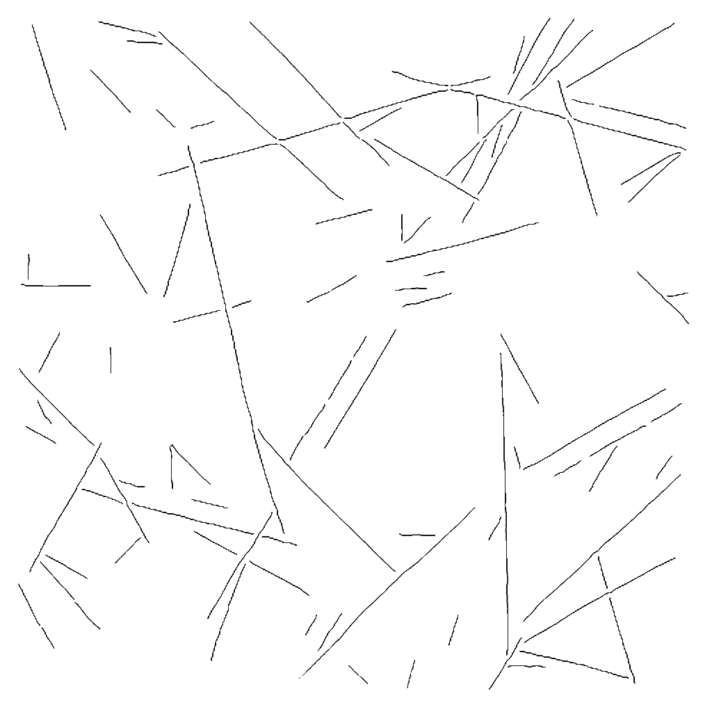
P.S. I’ve tried various parameters and this is the best result I got, but I was wondering if it should be better or if I’ve set the parameters correctly.
Skeleton extracted with photoshop:
(upload://8Ci2fV7HiJgSNdtxlCAulsMR6KD.jpeg)
Parameters:
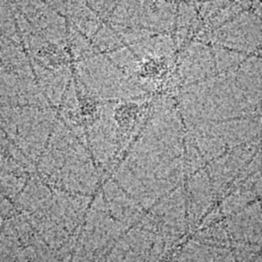
Micrograph:
-
Pixel size: 34.48 A
-
Acceleration voltage: 300 kV
-
Spherical aberration: 2.7 mm
-
Total exposure dose: 0.668 e/A^2
Filament tracer:
- Filament diameter (A): 34.48
 -Separation distance between segments (diameters): 100

 - Minumum filament length to consider (diameters): 40

 - Angular sampling (degrees): 15

 -Minimum filament diameter (A): 1100

 -Maximum filament diameter (A): 2200
Hey @aaron.p.p,
Thanks for giving more details! I do think recreating the skeletons in a notebook is a more systematic way to go about this. The result you have via photoshop is good — though I worry about issues with keeping the cropping parameters consistent between this image and the image of the manually drawn filament from the other software. In a previous comment, the fields written out by the filament tracer are described here: Transferring helical coordinate picks to Relion - #5 by mmclean – I’d take a look at the descriptions for the following fields of the particle dataset:
filament/position_Afilament/filament_uid
You would also need the following fields from the particle dataset:
location/micrograph_uid: unique identifier for the micrograph that this particle was picked fromlocation/center_x_frac: x-coordinates of the particle pick, in units of fractional distance along the micrographlocation/center_y_frac: y-coordinates of the particle pick, in units of fractional distance along the micrograph
To recreate the skeletons in a notebook, I’d follow the steps roughly:
- Load the outputted particle and micrograph datasets from filament tracer into a jupyter notebook via cryosparc-tools
- Partition particles into groups based on their
location/micrograph_uid. This can be done using the split_by method of the Dataset class
- Each group above now corresponds to the picks from a micrograph. For each of these groups, further partition them based on their
filament/filament_uid, using split_by. This is a field that contains a unique ID number for each filament.
- Use
filament/position_A to sort these picks in ascending order. This could be accomplished using numpy.argsort and the Dataset take method
- For all the picks in a filament (i.e. all the picks in the second set of subgroups), multiply
location/center_x_frac by location/micrograph_shape and likewise for the y coords. This will give you the coordinates of the pick locations for that filament.
- Now you have a list of coordinates, in the original shape of the micrograph, that define every filament. Connecting subsequent coordinates in this list with a line would give you the skeleton. But, depending on how you are computing the metric above, perhaps it isn’t necessary to re-convert these into an image of the skeleton and maybe it’s possible to work directly with these coordinates. If you need an image, you could look into image libraries like PIL (specifically the ImageDraw class and the line function may be helpful). It would be important to ensure images are saved to an adequate resolution and the aspect ratio and alignment of the images are identical when comparing
I hope this helps, and let us know if you have more questions!
Best,
Michael
2 Likes
Sorry for the delay in replying. I got it.
Following your steps using crysparc-tools, I was able to obtain the filaments (more or less, not all of the ones shown in the image above are shown, but is something).
Thank you very much!
1 Like