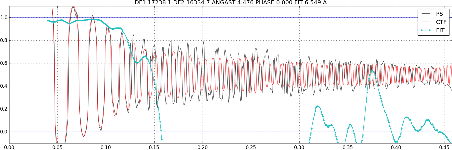
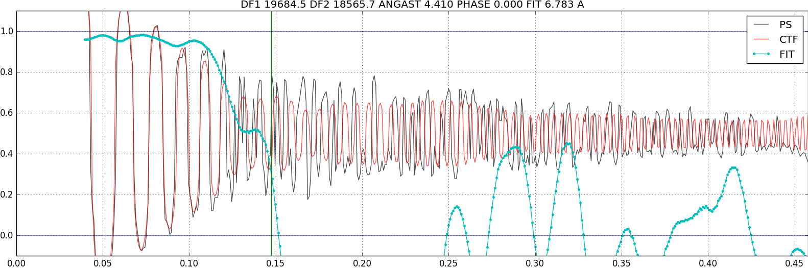
I have a question about the CTF fits that I have been getting using patch CTF estimation in cryoSPARC version 2.13.2. As shown in the screenshot below I am getting what appear to be acceptable fits until around 7Å. However, at higher resolution it does not appear to fit the CTF despite the presence of signal. I have collected a similar sample (same protein and grid type with similar ice) on another microscope without CTF issues. The sample was collected on C-flat grids on a Titan Krios with a Falcon III detector. I have double checked the pixel size, accelerating voltage, and Cs values.
Any suggestions on avoiding this situation in the future and/or improving the CTF fit for this dataset would be greatly appreciated.
Was this data tilted, or was it phase plate data?
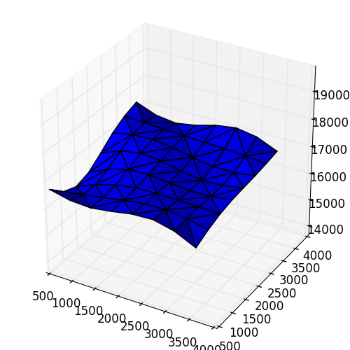
When you see the “3D” plot from patch CTF, does it show a large variation in the defocus landscape of the micrograph?
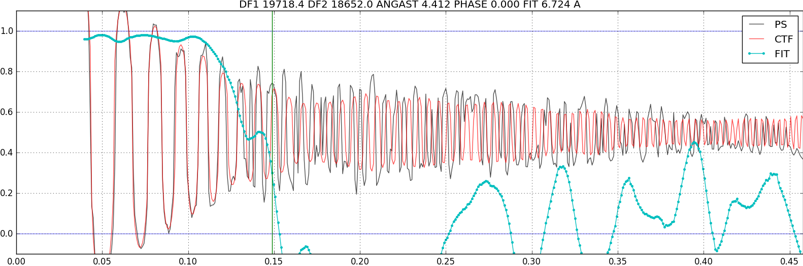
Can you try the following (this will force the job to assume the micrograph is flat):
clone the patch CTF job
set the “Number of movies to process” to 10 or so just for testing
set the “Override Knots X” and “Override Knots Y” both to 1 (there are advanced params)
Thanks for your reply. This collection is not from a tilted or phase plate data collection. Here is the 3D plot that goes with the patch ctf fit image that I posted previously:
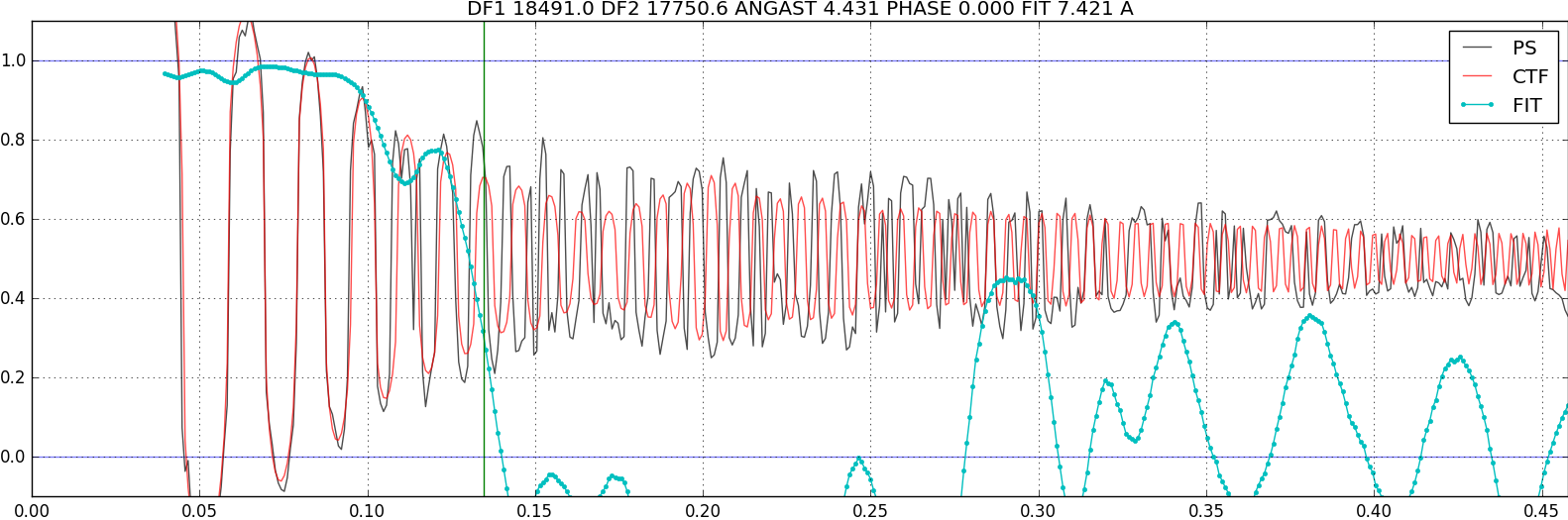
I just tried the job you suggested where the micrograph is assumed to be flat. As you can see below I am still getting a similar issue.
Hi @Andrew,
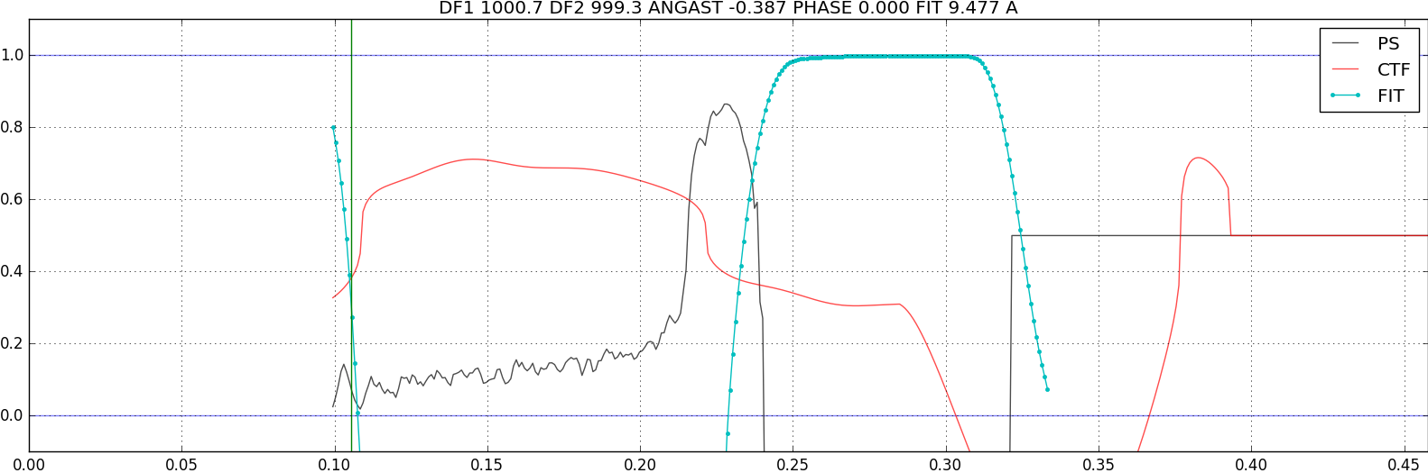
This is interesting… based on the 1D plots, there seems to be signal that is creating coherent Thon rings to quite high resolution. Can you try changing the “Minimum resolution (A)” parameter to something like 10A or 8A ? this will cause the fit to only look at the high resolution information.
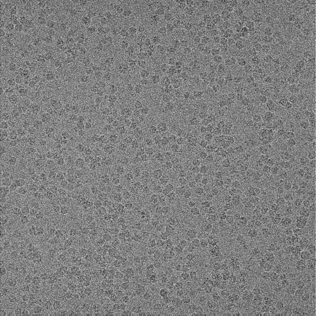
Can you also provide a few example images of the micrographs? It may be that you have ice/aggregates/carbon edges that are at a different height (defocus) on average than the particles… this would cause the low-res CTF to not match the high-res CTF.
Hi @Andrew, thanks for sharing.
Unfortunately based on this result, I’m not sure what to suggest next… the 4-10A result seems quite poor, and maybe something has gone wrong there… would you be open to share a few of these troublesome micrographs with our team (confidentially) so we can debug?
@JunhoeK Try running CTFFIND4 (within cryosparc) on some of the “bad” micrographs and see if the fit is any better. Also, carefully double check the pixel sizes and Cs you gave during motion correction or data import.
With CTFFIND you will also be able to see the 2D power spectrum / CTF comparison. Do the power spectra really have visible Thon rings to very high resolution? Is there significant astigmatism, perhaps affecting the 1D radial averages? Does running CTFFIND4 in exhaustive search make a difference? (Note CTFFIND4’s “rapid” search should be the default, it’s generally better than exhaustive search, not just faster, because of how astigmatism is treated using Marin’s trick).
Sometimes the best explanation is simply that the micrographs aren’t that good, for one of the many possible reasons. The CTF envelope can be poor even if you think the particles “look OK.”
I just experienced something similar. It worries me more however, that CSLive gave me a 2.5-4A CTF res fit, whereas CS Patch CTF estimation 5.5-8A CTF res fit. I am using CS v4.0.3. Does anyone know what could be the issue?
Playing around with the Minimal resolution or with override knots doesn’t improve the results. CTFFIND is even worse, sometimes estimates a 700A fit.
I also tried out the classic mode of Patch CTF estimation, which gives me the same results.
Mistery solved. While I entered the correct spherical aberration in live, I left out the decimal mark in regular cryoSPARC. I corrected, and now everything is fine. It was my mistake.